Flying Shear Solutions Software
The Flying Shear (also known as flying knife) is a common industrial application for cutting a continuous product to a set length at line speed. This means that the main production process is not interrupted, and so machine productivity is maximized.
How does the Flying Shear Solutions software work?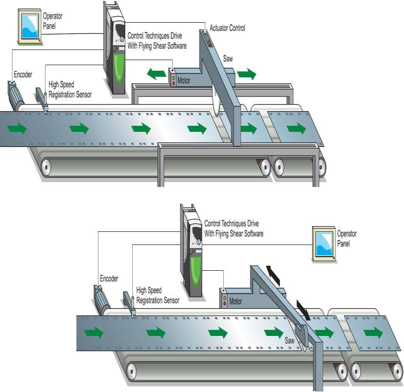
The cutting tool is typically mounted on a carriage that moves either parallel to the product flow or at an angle across the product flow. The Flying Shear drive accelerates the carriage to synchronize with the line speed, at this point the cut tool can be activated. The carriage then decelerates and returns to it’s original position ready to cut again. There are also many other similar applications where a carriage must be synchronized at line speed and most of these can also be accommodated using the Flying Shear control software.
The drive is configured using engineering units of choice such as mm or inches. This means that configuration of the system is made very easy, through an operator interface or by entering configuration parameters directly on the drive.
The fly profile is optimized for each application by breaking the synchronized, part of the profile down into three areas: settling time, cut time and tool rise time. These are entered in milliseconds. The drive will then calculate the profile and perform checks to ensure that the parameters entered are achievable, given the length of motion available, and also the required cut length.
Typical applications for Flying Shear
Typical applpications include various types of cut-to-length machines, printing, packaging, depositors, punches, product inspection, or any other process where synchronization at line speed is required.
What functions offers the Flying Shear Solutions software?
The Flying Shear Solutions software has the following features:
- Easy configuration
- Hardware and software limits
- Fieldbus interfaces are available such as EtherCAT, Ethernet /IP, CTNet, PROFIBUS-DP, DeviceNet, INTERBUS and CANopen
- Manual jog functions Homing modes, on switch or with switch and Marker pulse
- High speed output is used to initiate the cut
- Registration capture, with windowing
- Batch control functions
- Dynamic motion profile changes to cut length etc.
- Real engineering units are used. Units are defined for the master and slave axis, as the number of encoder counts per unit
- Resolution of the cut-length may be entered to within 0.001 units
- Tool width compensation
- Profile optimisation reduces the machines mechanical stress: The return profile can be calculated to operate at the slowest speed and acceleration rate, and yet with sufficient time to achieve the next cut, either triangular or trapezoidal profiles are used
- A range of tool control modes
- Gap control for spacing of product after-cut
- Parallel and angled carriage applications are handled
- CTIU HMI support
- Can be used with SM-Applications Plus or SM-Applications Lite V2 second processors with SM-Universal Encoder Plus or SM-Encoder Plus options