

According to a commonly consulted hierarchy of controls, people’s safety in the workplace is dependent on various types of protective measure. The most effective of these is classed as hazard removal – obviously enough. At the other end of the scale is the wearing of personal protective equipment. Midway between the two lies the field of engineering controls – the design or adaptation of machinery to isolate the worker from risk.
This category comprises a broad variety of engineering ideas. Lifts and platforms help keep people from falling (or from being fallen onto). Sacrificial parts such as fuses or rupture discs are designed to protect machines by failing under stress. Ventilation systems make sure atmospheres are clean and safe to breathe.
Machine safety systems in manufacturing
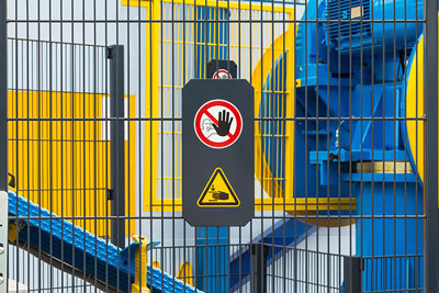
Machines with rapidly moving parts, such as flywheels, drive belts and fan blades, pose a particular hazard, and, where they are feasible, guards to prevent contact with body parts are a legal requirement. These guards range from appropriately fabricated hoods and shields to, in the case of robots and other larger machines, wire perimeter cages.
Where human intervention in the equipment is called for, in order to carry out inspection or repair, it is essential that dangerous machinery is deactivated and kept safely turned off. A number of devices are traditionally used to carry out this procedure. Most commonly, electrical interlocks attached to access gates automatically disable machinery when gates are opened.
Light bars and curtains perform the same function for smaller machines or where mesh cages would otherwise be inappropriate. (The electrical circuit is interrupted when a person breaks a field of light projected between two points.) Pressure mats are another frequently used presence detection device.
Such a safety system conventionally operates by means of a series of hardwired electromechanical components: switches, relays, contactors, encoders and so on. Increasingly, however, the safety controls enacted by these external devices are being integrated into the programming of variable-speed drives.
Drive-based safety systems are less complicated and time-consuming to install than their non-digital predecessors. They avoid the additional electronic structures required by traditional fail-safe mechanisms and are less vulnerable to parts failure. With simpler and speedier reset procedures, moreover, expensive downtime can be minimised.
Drive-based safety systems in manufacturing machines
Like all aspects of machine engineering, drive-based safety functions must operate to a certain level of reliability. Standards devised by bodies such as the International Electrotechnical Commission inform legislation produced by the European Union and other authorities around the globe. In order to meet the safety criteria required by the EU Machinery Directive 2006/42/EC, the functional safety of variable speed drives must accord with product standard EN/IEC 61800-5-2.
The safety measures a drive-based system can bring to operations cover a range of hazard responses. The fundamental function, and that most commonly used, is the Safe Torque Off (STO) signal. This simply switches off the torque-generating energy supply to the motor. How quickly the machine stops will depend on load or friction, and it is guaranteed against unexpected restart.
Where mechanical action must be halted in a controlled manner the Safe Stop 1 (SS1) function instructs the drive to ramp speed rapidly down to a standstill before automatically activating STO. This suits the emergency stop requirements of heavy spinning equipment such as saws, grinding machines and rolling mills.
Safe Stop 2 (SS2) works in the same way except that, after braking, the motor is held in a Safe Operating State. Using this function to keep full torque available from the motor may be necessary to hold equipment parts steady that would otherwise fall out of position.
In the case of machinery such as cranes and hoists that deal with very heavy loads a Safe Brake Control (SBC) is used to activate a mechanical holding brake at the same time as the main drive is deactivated by the STO signal.
Thanks to the Safely-Limited Speed (SLS) function, machinery can be made to run below a specified limit. As monitored by the drive, a speed that exceeds that limit will automatically trigger an emergency stop through an STO or SS1 signal.
The SLS function is particularly useful in the set-up and maintenance of equipment where, for example, cables need to be manually fed over turning wheels or drums. It is also generally a way of minimising loss of work. Rather than shutting a machine down completely when an operator is in the vicinity of equipment, it can be used to proceed with production at a reduced, safe rate until the operator enters a specific danger zone (at which point power is cut).
And because sharp drops, as well as surges in power, can cause some machines to behave dangerously, a lower speed limit may be programmed in conjunction with an upper limit by means of the Safe Speed Range (SSR) function.
Having this range of safety controls available, individually or in combination through plug-in modules and fieldbus modules, gives the automation designer significantly more flexibility and freedom than previously. And with status information available in the drive interface, the operator has a reliable system overview extending to timely and accurate diagnostics.
Its intelligent and adaptable character ultimately means that a drive-based safety system is as capable of pre-empting mechanical dangers as it is effective at responding to them. The consequent benefits to the workplace, not just in terms of safety but in those of streamlining design and enhancing overall efficiency, make it a natural component of automated industry.