Here Jacques Saint-Michel, scientific director for Leroy-Somer, explains the theories behind cogging torque.
The achievement of low and repeatable values of cogging torque probably is the major problem encountered in designing and manufacturing permanent magnet motors. Although finite element methods show that cogging cancellation is theoretically always possible, if the dimensions of the magnets are carefully determined, experimental results are very often disappointing, and sometimes so far from the objective that some motors have to be rejected. This paper tries to bring some understanding about that situation and to quantify the influence of some geometrical defects.
1: The origin of cogging
Obviously, the cogging torque results from the combined influence of the interaction of each individual magnet with each individual tooth. To analyse that, we shall make the assumption that the magnetic circuit is linear (unsaturated), which is a reasonable assumption at no load, to allow the use of the superposition principle.
We shall then look first at the following situation:
¤ all stator teeth are perfectly identical, and evenly spaced.
¤ only one magnet has been placed on the rotor.
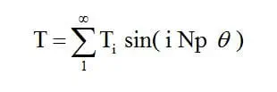
In that particular condition, it is clear that the magnet on the rotor will have a stable position in front of each stator tooth. Let Ns be the number of stator teeth; the torque T can then be written as:

where ø represents the position of the magnet. All harmonics, either odd or even, may be present, the first one being by far the largest one.
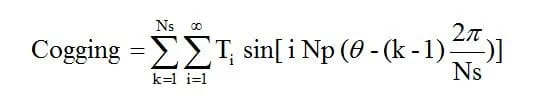
To deal with all the magnets, as the magnetic circuit has been assumed linear, it is possible to add all the corresponding contributions. Let Np be the number of poles; then, if the magnets are evenly distributed and spaced by , the cogging torque is given by:

This general expression, valid if the teeth and the magnets all are in their right position, will be useful to analyse the frequency components of the torque. This will be illustrated by a few examples hereafter. However, for a better understanding, it is easier to consider the vector approach, as is usual in electrical engineering. Each sine component is considered as the projection on a fixed axis of a revolving vector, angular speed of which being related to its harmonic order.
Example 1: machine with 18 teeth and 6 poles:
Replacing Ns by 18 and Np by 6 leads to the following:
¤ for any harmonic order Ti , the vectors representing the contribution of each magnet are shifted by a multiple of , and are then in phase concordance, leading to a zero sequence situation.
¤ all these vectors will then directly add, the total cogging being the sum of all the contributions of all the magnets. It is obviously the worst case that can be encountered, and one can conclude that for this kind of machine, the cogging is intrinsically very high, making skew absolutely necessary.
Example 2: machine with 21 teeth and 8 poles:
Here the situation is quite different, because 21 and 8 have no common divider. Then, for most of the harmonic orders, the corresponding space vectors form a balanced multiphase system ( here with 8 phases), either positive or negative sequence, the sum of which is zero. So, the total contribution of those harmonic orders disappears.
However, some harmonic orders will lead to a zero sequence situation, where all the vectors will directly add. The lowest frequency order corresponding to that will occur when:
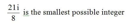
which obviously occurs when i = 8. Then, the fist frequency in the cogging waveform will be 21 x 8 = 168 times the mechanical speed, and the amplitude of that contribution will be given by 8 x T8 .
This amplitude is likely to be very low, resulting from a fairly high harmonic order.
Example 3: machine with 12 teeth and 8 poles:
The situation here is, in some way, similar to the preceding one, with the difference that 12 and 8 have 4 as a common divider. Consequently, the first frequency in the cogging waveform will occur when:

which occurs when i = 2. The first frequency in the cogging waveform is then 12 x 2 = 24 times the mechanical speed, and the amplitude is now 8 x T2 . If the magnets are not carefully shaped, this amplitude is likely to be quite high, but if T2 can be minimised by shaping, the theoretical value of cogging at that frequency can be made very low.
Remember that this analysis is valid when the geometry of the motor is mathematically perfect, which of course cannot be true in practice. We are, however, now able to deal with geometrical defects, as for instance bad position of one magnet or one stator tooth..
2: Influence of the magnet position
We can very easily follow the same procedure, assuming now that the magnets are not evenly spaced, that is to say not shifted by exactly jsm7one from the other.
To illustrate that, let us take again the example of a 12 teeth 8 poles machine, and consider the influence of the first harmonic order T1 .
If only one magnet is not in its right position, by an arbitrary mechanical angle, the space vector corresponding to the wrong magnet will be shifted by degrees from its right position. Six of these vectors will fully compensate each other, because they are alternatively in phase opposition, and it will remain the sum of 2 vectors, of same amplitude T1 , but with a misalignment of degrees. The resultant of that is given by:
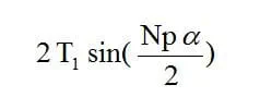
which is the amplitude of the cogging, at the frequency of Ns times the mechanical speed, that is to say the teeth frequency. This value can be very large, since T1 is the largest component in the single magnet torque waveform.
If a is 1°, the cogging will be as high as 0.21 T1 , which can be very large.
Note that for a rotor diameter of 25 mm for instance, 1° corresponds to 0.22 mm at the periphery of the rotor, which is not a very large geometrical defect.
Resulting cogging will be at tooth pass frequency.
3: Influence of the teeth non-equidistance
Improper location of teeth may also be another important issue, especially for the segmented construction where some uncertainties can occur during the assembly process.
To look at that, one can follow a similar procedure to that developed in the first paragraph, with the difference that we now will assume that all the magnets are present on the rotor and evenly spaced, and the stator has only one tooth.
The torque due to that single tooth can be written as:
in which Np now appears instead of Ns, and where Ti values are different from the previous ones.
The total torque, when all the teeth are present, is now:
when teeth are evenly distributed.
A similar analysis can be conducted. If one tooth is shifted from its right position, a residual torque will appear, at the pole pass frequency.
Its amplitude will be given by:
Again, this can lead to quite unacceptable values.
As a conclusion, motor designers of course need to carefully optimise the machine geometry, including number of teeth, number of poles, magnet shaping, and also possibly some mitigation means such as helical skew, or step skew for instance.
But this is not sufficient. Designers must also investigate on sensitivity of any possible geometrical defect, or magnet strength dispersion, etc.…