Freight In-Ground
- Overview
- Specifications
- Diagrams
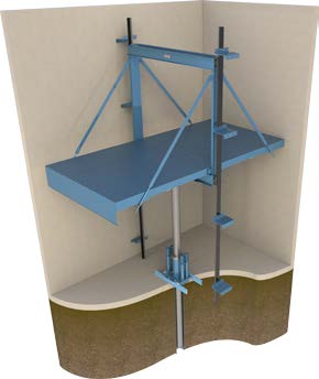
Traditional design utilizing a hydraulic jack, which is located directly under the platform and installed in the ground.
Advantages:
- Generally the least expensive and easiest to install
- Offered in both low and high capacity elevators
- Accommodates front and rear opening configurations
- Minimal pit and overhead requirements
Disadvantages:
- The jack must be buried into the ground roughly the same distance as the overall travel.
- Drilling a hole can be expensive and difficult depending on ground water and bedrock.
- Possible ground contamination from oil leak (sealed PVC recommended to prevent contamination)
Freight In-Ground Hydraulic
| Loading | Capacity (lbs) |
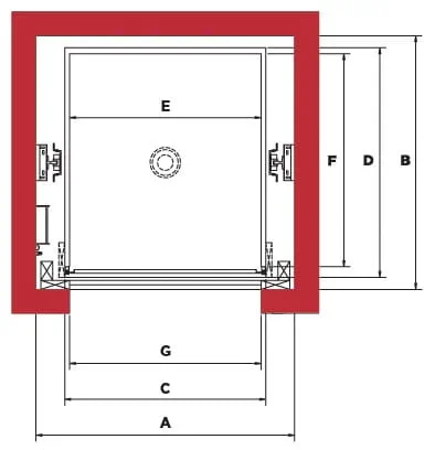
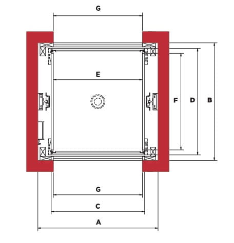
Hoistway - Width x Depth |
Platform - Width x Depth |
Inside Cab Width x Depth |
Door - |
Front/ Rear |
Pit Depth |
AutoCAD | |
| Class A | 4000 | 9'-0" x 9'-4" | 7-'0" x 8'-6" | 6'-8" x 7'-11" | 6'-8" x 7'-0" | Front | 4'-6" | .dwg | |
| 4000 | 9'-0" x 9'-4" | 7'-0 x 8'-6" | 6'-8" x 7'-9" | 6'-8" x 7'-0" | Front/ Rear |
4'-6" | .dwg | ||
| 5000 | 10'-0" x 9'-10" |
8'-0" x 9'-0" | 7'-8" x 8'-5" | 7'-8" x 7'-0" | Front | 4'-6" | .dwg | ||
| 5000 | 10'-0" x 9'-10" |
8'-0" x 9'-0" | 7'-8" x 8'-3" | 7'-8" x 7'-0" | Front/ Rear |
4'-6" | .dwg | ||
| 6000 | 10'-4" x 10'-10" |
8'-4" x 10'-0" | 8'-0" x 9'-5" | 8'-0" x 7'-0" | Front | 4'-6" | .dwg | ||
| 6000 | 10'-4" x 10'-10" |
8'-4" x 10'-0" | 8'-0" x 9'-3" | 8'-0" x 7'-0" | Front/ Rear |
4'-6" | .dwg | ||
| 8000 | 10'-6" x 12'-10" |
8'-4" x 12'-0" | 8'-0" x 11'-5" | 8'-0" x 7'-0" | Front | 4'-6" | .dwg | ||
| 8000 | 10'-6" x 12'-10" |
8′-4″ x 12′-0″ | 8'-0" x 11'-3" | 8'-0" x 7'-0" | Front/ Rear |
4'-6" | .dwg | ||
| 10000 | 12'-8" x 14'-10" |
10′-4″ x 14′-0″ | 10'-0" x 13'-5" | 10'-0" x 7'-0" | Front | 4'-6" | .dwg | ||
| 10000 | 12'-8" x 14'-10" |
10'-4" x 14'-0" | 10'-0" x 13'-3" | 10'-0" x 7'-0" | Front/ Rear |
4'-6" | .dwg | ||
| Class B | 8000 | 10'-6" x 22'-6" |
8'-4" x 21'-8" | 8'-0" x 21'-1" | 8' x 8" | Front | 4'-6" | .dwg | |
| 8000 | 10'-6" x 22'-6" |
8'-4" x 21'-8" | 8'-0" x 20'-11" | 8' x 8" | Front/ Rear |
4'-6" | .dwg | ||
| Class C | 8000 | 10'-6" x 12'10" |
8'-4" x 12'-0" |
8'-0" x 11'-5" | 8'-0" x 7'-0" | Front | 4'-6" | .dwg | |
| 8000 | 10'-6" x 12'10" |
8'-4" x 12'-0" | 8'-0" x 11'-3" | 8'-0" x 7'-0" | Front/ Rear |
4'-6" | .dwg | ||
| 10000 | 12'-8" x 14'10" |
10'-4" x 14'-0" | 10'-0" x 13'-5" | 10'-0" x 7'-0" | Front | 4'-6" | .dwg | ||
| 10000 | 12'-8" x 14'10" |
10'-4" x 14'-0" | 10'-0" x 13'-3" | 10'-0" x 7'-0" | Front/ Rear |
4'-6" | .dwg |
Additional Specs
Hole Depth = Travel + 6′-0″
Speed available to 150 FPM
Minimum Overhead = (Door Height x 1.5) + 9″
This information is intended for preliminary planning. We have attempted to include the basic data that you will require in your planning efforts. For details about specific or custom installations please contact your local Canton Elevator representative, or contact us directly.