In the second part of this mini-series, Colin Hargis looks at the effective management of harmonics.
Harmonic measurements
Individual harmonic currents or voltages can be measured and quoted in r.m.s. quantities. Often they can be expressed as a percentage of the fundamental. It is very common for harmonic measuring instruments to give harmonics as a percentage, by default.
Care must be taken in assessing harmonic data, especially current data. If the fundamental current is low, because the load power is low, then the harmonics expressed as a percentage will appear high. This can be misleading. The data provided for the drive will be at a defined load power. At reduced load, the harmonic currents reduce in absolute value, but as a percentage of the fundamental they increase.
This is illustrated in Figure 7. Figure 7(a) shows how the current and major harmonics such as the 5th and 11th increase as the power increases. Figure 7(b) shows how the major harmonics and the THD, when expressed as a percentage of the fundamental, fall as the load power increases.
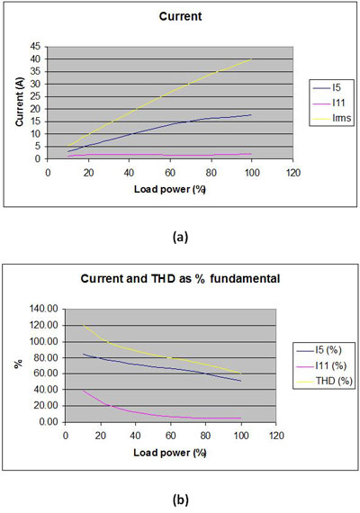
Figure 7: Variation of current and harmonics with load power, expressed as (a) absolute quantities and (b) % of fundamental current
In a drive this can be particularly misleading if the user fails to appreciate that the input current is a function of the power, that is the product of torque and speed at the shaft. If a drive is delivering rated torque at reduced speed then it may appear to be “working hard” because the output current is close to its maximum rating, and the inverter stage is carrying that current and producing the expected power loss as heat. However the actual power throughput is low, and so the input current will also be low.
THD, VTHD, ITHD, distortion factor and power factor
A simple single parameter to measure the overall effect of harmonics is the Total Harmonic Distortion, THD. This is the ratio (in %) between the r.m.s. value of all the harmonics together, and the fundamental. For voltage and current it may be referred to as VTHD and ITHD respectively.
Again care must be taken with ITHD, because at reduced load it will appear high.
In power engineering the power factor is commonly used to measure the reduction in useful power conveyed by an alternating current if it is not in phase with the voltage.
When current and voltage are sinusoidal this is equal to cos o.
In the presence of harmonic current, and assuming the voltage remains sinusoidal, the power factor can be broken down into two factors:
![]()
Where the distortion factor measures the reduction in useful current caused by distortion:
And the displacement factor measures the reduction caused by the phase shift:
The meaning of these factors can be illustrated by considering a motor operating either direct from the power line, or with a drive:
![]()
So the motor has a very similar power factor in both cases, which means that the full-load current drawn from the mains supply is very similar. However with the motor alone the increased current is entirely because the current lags the voltage in phase, whereas with the motor and drive this is mainly because there is harmonic current.
Distortion factor and THD are alternative measures of the level of distortion, or total harmonics. They are related by the following function:
(where THD is expressed as a fraction, not percent)
Management of harmonics. Harmonic current data for products.
The electricity supply utilities operate rules to protect the power system and power users from excessive harmonics. Each power user is responsible for ensuring that they comply with the rules. In some regions such as the European Union, emission of harmonics from electrical products which are used in large numbers is regulated as part of the EMC law. This means that domestic and small business users do not have to make any special provisions. Large industrial users of specialist equipment have to ensure for themselves that their harmonic emission is not excessive. Most commonly, the rules are applied when a new installation is proposed which requires a new power supply from the utility, as a condition of providing that supply.
The rules vary between countries, but the principles are the same. The key stages are shown here:
- The power utility ultimately has to ensure that the harmonic voltage in its supply meets the acceptable level. For example, in the EU power quality is governed by a standard EN 50160. Generally it allocates a harmonic voltage “budget” to each user. As explained previously, the harmonic voltage is caused by the harmonic current interacting with the supply impedance and the existing harmonics, which are unique for every location. It requires some complex calculations and measurements predict it, which is not justifiable for typical industrial installations.
- Therefore generally the utility has some simplified rules which allow harmonic current to be accepted up to a limit, which might depend on the capacity of the supply connection, or the user’s peak or average current demand. It is much simpler to estimate current than voltage, by adding the harmonic current data for all relevant equipment connected to a particular supply point. For this reason, professional equipment such as drives which generates significant harmonic current needs to have the harmonic current data available to the user. Control Techniques provides this data for all of its drive products in the EMC data sheets which are freely available on request.
- For a given installation, if the current exceeds the permitted limits then either technical measures must be taken to reduce it, or a more complex investigation must be undertaken to assess the harmonic voltage caused by the installation.
- Meanwhile, if all of the equipment meets harmonised standards in a single market such as the EU, none of the work described above is necessary.
Standards
For installations, many utilities operate their own regulations so there are very many national standards. One particularly well-known standard is IEEE 519.
Power quality standards include IEC 61000-2-4, which defines “compatibility levels” which are maximum permitted harmonic levels, in this case for industrial LV supplies. IEC standards are not mandatory, but utilities often use the limits given in the IEC standards as the starting point for their own regulations.
For end products, there are IEC standards IEC 61000-3-2, for equipment rated up to 16A per phase, and IEC 61000-3-12, for up to 75A per phase. The European versions such as EN 61000-3-12 are in effect mandatory for end products placed on the market in the EEA.
If a drive is built in to equipment which falls within the scope of one of these standards then it is quite likely to be a major contributor to the harmonic emission. For Control Techniques drives it is necessary to use small additional input chokes in order to meet EN 61000-3-12. Information is given in the EMC data sheets.
Effect of load
A common issue encountered when checking for harmonics compliance of machinery containing drives is the matter of the correct rated load power. We have had complaints of products failing the test where it has turned out that the test load was less than the rated load. This might be because the application does not use the full capability of the drive, or because it was not possible to load the machine fully in the EMC test laboratory. It is often difficult to create a realistic load in a test lab because machines often are intended to work on large, dirty or difficult materials which cannot be brought in to the lab. In order to ensure that the required standard is met, the following requirements have to be observed:
- The additional input chokes must be selected to be correct at the intended maximum continuous load power for the application, which is not necessarily the drive rating.
- Account must be taken of any other harmonic-generating equipment in the machine.
- The load during the test must be equal to the rated load. If necessary some kind of temporary brake or other load device must be provided in the test jig.
Reducing harmonics
The natural level of harmonics generated by a simple rectifier can be much reduced by the addition of inductance. This can be in the drive DC link or in the AC input lines. Most drives rated above about 2.2 kW use a three-phase supply and contain chokes to provide the inductance. Figure 8 shows a typical current waveform for this kind of drive. You can see that the waveform is much better than in Figure 1, although it is far from sinusoidal. In this case the ITHD is about 50% and the worst harmonic is the fifth at about 40%.
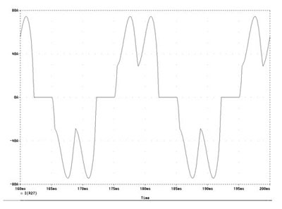
Figure 8: Typical input current waveform for drive with three-phase supply and input chokes.
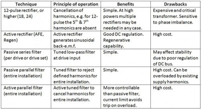
This level of harmonics is suitable for the majority of applications over a range of powers from 3 kW to several hundreds of kilowatts. For sensitive applications, and where the total drive power begins to approach the capacity of the supply, it may be necessary to make further reductions in harmonics. The table below gives the main techniques available with some notes on their relative advantages.
Swinging chokes
The use of a “swinging choke” has been promoted by some drive manufacturers. The swinging choke is an invention from the 1920s, where it was used in some radio sets for DC smoothing. The choke is designed with a stepped or profiled air-gap so that as the DC current increases, part of the magnetic circuit saturates and the inductance reduces. The result is that at low currents the inductance is increased, and this helps to counteract the problem described above, of meeting harmonic limits over a range of load powers. This is because the inductance value adapts itself to the load.
The swinging choke can benefit the drive manufacturer, because it can allow the stock of different choke values for a variety of drive ratings to be reduced. It may benefit the user by allowing the drive to meet a harmonic standard at reduced load without an additional choke being required. In practice it is quite difficult to design a swinging choke which works over a wide load range, so the real benefits are small.
Browse all Technical blog posts