This blog looks at the subject of flicker, which can be seen as a matter of power quality or of Electromagnetic Compatibility (EMC) depending on your point of view. We will consider whether variable speed drives can cause flicker and also where they can help to solve a flicker problem.
“Flicker” refers to the effect on electric lighting when the supply voltage varies quickly. This can be anything from an occasional single dip or flash when a large load is connected or disconnected suddenly, through to an irritating rapid flicker if the voltage is modulated at a frequency in the range where the human eye and brain are particularly sensitive, which is around 0.5 Hz to 20 Hz.
Flicker is sometimes confused with harmonics and other power quality issues. Harmonics are by definition at frequencies which are integer multiples of the supply frequency, and they are much too high for the eye to respond. However both flicker and harmonic voltage are caused by load currents affecting the voltage because of the supply source impedance, so in locations where the supply impedance is high, because of a long supply line or some other factor, problems of both harmonic voltage and flicker can occur together.
Figure 1 shows an exaggerated waveshape with simulated flicker at one fifth the supply frequency. By contrast Figure 2 shows a simulated fifth harmonic. In Figure 2 every cycle is distorted but the same shape, so no flicker occurs.


Electrical power suppliers have to ensure that their power quality is fit for purpose, and they have guidelines for flicker. Generally they only carry out measurements if there is a complaint, there is rarely any kind of routine testing of installations except for some special systems such as wind turbines.
Electrical products which are manufactured in large numbers may have to meet product standards for flicker. The best known international product standard is IEC 61000-3-3, or for Europe EN 61000-3-3, which gives tests and limits for products rated up to 16 A per phase. In the European Union this standard is harmonised under the EMC Directive, so that equipment within its scope generally has to comply with it in order to carry the CE mark and be placed on the market in the EU. For rated current up to 75 A, IEC 61000-3-11 applies. The standards have strict limits in the sensitive 0.5 Hz – 20 Hz repetition frequency range, but no limits above 25 Hz.
The standards for flicker all require a measurement and assessment which takes account of the dynamic behaviour of electric lights and the sensitivity of the human eye and brain. The flicker curves (see later) are based on tungsten filament light bulbs. These are rather sensitive to voltage because of the square law relation of voltage and power. On the other hand the thermal mass means that they tend to smooth out rapid fluctuations. Of course filament bulbs are becoming uncommon now. Fluorescent lamps have a different characteristic with less smoothing effect. LED lamps often have a regulator so they are unaffected by voltage, except when they are designed to be used with a dimmer. The standards might be updated in future to reflect the behaviour of modern lamps, but the cost of changes in replacing test equipment and re-testing products is unwelcome. It is likely that the limits based on filament bulbs will be with us for some years to come.
Interharmonics
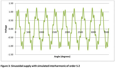
Interharmonics are unwanted frequencies which are not at integer multiples of the supply frequency, so they lie between harmonics in the spectrum. If they are close to a true harmonic then they can result in an apparent modulation of the supply voltage. In a simple resistive load like a filament lamp they do not cause flicker because their frequency is high and the lamp is only sensitive to the running average of the r.m.s. voltage. However a rectifier or other non-linear load can generate sum-and-difference frequencies which can include low frequencies if the interharmonic is close to an integer multiple of the supply frequency. Figure 3 shows an example where the interharmonic is of order 5.2. The peak amplitude is visibly modulated, but the r.m.s. voltage is not, and this will not be measured as flicker. This kind of waveform can occur with regenerative drives or other active power controllers where the switching frequency is not phase-locked with the supply.
Continuous development
Flicker is always caused by a variation of current drawn from the supply, resulting in a variation of supply voltage which then affects other loads including lighting. There are many possible sources, the list below shows some of the more common ones.
Single events:
- Starting motors direct on line. This is by far the most common cause of single voltage dips. An induction motor draws between 3 and 5 times its rated current when starting, and the effect on voltage is made worse by the fact that the starting current lags the voltage in phase so that the voltage drop in the supply impedance, which is usually predominantly inductive, is greater than for a resistive load.
- Starting large electronic devices such as drives, with capacitor charging inrush current
- Starting large transformers with magnetising inrush current
- Starting compressors or pumps with back-pressure, causing a high starting torque
Frequent random events:
- Arc furnaces
- Arc welders
- Machinery subject to frequent heavy load peaks, e.g. mixers, presses etc.
Periodic or nearly periodic events:
- Automatic spot welders
- Reciprocating pumps or compressors, or similar pulsating loads.
- Thermostats or other controllers which work by switching the load – especially with solid-state switches which can operate frequently.
- Burst-firing thyristor or triac controllers
The effect of variable speed drives on flicker
The drive itself
The only way a drive can cause flicker in itself is through the capacitor charging inrush current when power is applied. Control Techniques drives are designed so that the inrush current does not exceed the rated input current, so the voltage dip does not exceed that caused by normal running at rated power.
The control system
If the drive is in a system which causes the drive to generate a rapidly fluctuating power output then this can cause flicker. This could be caused by programmed periodic operation or by marginal stability in a feedback control loop. Any control system should be assessed to ensure that it will not cause excessive flicker.
In a machine with multiple axes and rapid periodic movements, it may be possible to arrange the control so that the power peaks occur sequentially. This could multiply the flicker frequency by the number of axes, which if it moves beyond 25 Hz could eliminate the problem.
The load
Motor starting
The drive completely eliminates the sudden voltage drop caused by motor starting. Not only does the motor frequency and voltage ramp up in a controlled fashion so that the motor current is limited, but also the drive input current is proportional to the output power, not the output current, so the input current ramps up only as the motor speed increases. There are applications where a drive is worthwhile purely for its benefit in starting without causing excessive voltage drop, if the alternative would be an expensive reinforcement of the supply system.
Pulsating loads such as reciprocating pumps
The drive has very limited stored energy in its DC link capacitor, not enough to smooth out a flicker cycle, so if the load power fluctuates then the drive input current fluctuates in the same way. Unless special measures are taken, the drive will not compensate for a fluctuating load.
Usually the drive simply makes no difference to the level of flicker caused by a pulsating load, but it is possible for a drive to make this effect worse:
- Firstly, by reducing the speed it may bring the pulsation frequency down below the critical 25 Hz point where flicker becomes perceptible.
- Secondly, if the drive system is configured to give close speed control with a pulsating load torque then it can enhance the power fluctuation, because it prevents the motor from slowing down and speeding up in the torque cycle. This reduces the benefit of the stored energy in the inertia of the machine, including the flywheel if fitted. Unless there is a very particular reason to control the speed closely within the torque cycle, it is not advisable to use closed-loop speed control or slip compensation with a pulsating load. It is actually better to allow the speed to vary with the torque in order to make use of the mechanical stored energy.
If closed loop speed control must be used, it is best to implement a predominantly integral controller with a low gain. In this way the average speed is controlled precisely, but the controller does not resist the natural periodic variation within a cycle caused by the induction motor slip. This suggestion appears counter-intuitive, since we tend to think of a variable speed drive as offering fast and accurate speed control, but actually fast-acting control reduces the benefit of the flywheel or other inertia in storing energy.
The above discussion applies with an induction motor. With a permanent magnet motor the speed is inherently closely regulated and torque pulsations are directly reflected as input power without any possibility of rotor slip giving some reduction. It is possible to programme a special control algorithm into a drive which deliberately allows the speed to fall dynamically as the torque rises, within a rotational cycle, whilst keeping the long-term average speed at the desired value. This tends to keep the power constant (power = torque x speed), and it is power which determines the input current. Control Techniques has a patented application for this. It is possible that this could give useful cost savings in the machinery design in some applications, for example a multi-cylinder reciprocating pump or compressor might be replaced by a single-cylinder one.
Flicker limits
Flicker is measured using a “flickermeter” defined in the standard IEC 61000-4-15. Limits for equipment are set in standards such as IEC 61000-3-3 and IEC 61000-3-11.
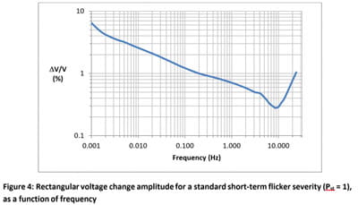
The flicker measurement is of the supply voltage fluctuation. For a product test, the test system has to include a simulated mains supply impedance, which is defined in the standard. The limits in IEC 61000-3-3 are based on a 230 V 50 Hz supply with an impedance of (0.4 + j0.25) W, which simulates a very “weak” supply, i.e. one with a low short circuit current.
Figure 4 shows the limit for simple repetitive rectangular voltage changes from IEC 61000-3-3, for a 230 V 50 Hz supply. The frequency axis represents complete cycles per second, i.e. each cycle comprises two equal but opposite steps. There are further rules for evaluating other patterns. The figure shows clearly the low permitted levels for the critical frequency range between about 0.5 Hz and 20 Hz.
Reducing flicker
We have already considered ways in which the use of a variable speed drive may help to reduce flicker from motor starting or from a pulsating load.
Conventional methods include the use of multi-cylinder reciprocating pumps to smooth out the torque, and flywheels.
Where a large power pulsation is unavoidable, the supply connection should be made electrically close to the site incoming power feed in order to avoid the voltage drop in cables shared with other loads. Lighting circuits should also be separately connected close to the incoming power feed.
In extreme cases it may be necessary to install a new supply with lower impedance. In view of the high cost, it is worth exploring the possibility that creative use of variable speed drives might avoid the cost.
Browse all Technical blog posts