Colin Hargis, chief engineer at Control Techniques, offers an introduction to harmonics in this two-part blog. Part two is available here.
This blog is an introduction to the subject of electrical power harmonics, with special reference to variable speed inverter drives. It aims to explain what they are and what they do in straightforward terms, and distinguish them from other Electromagnetic Compatibility (EMC) effects such as radio frequency interference and electrical “noise”.
For simplicity the examples mostly assume a 50 Hz supply frequency. If you work in an area using 60 Hz then you will need to scale the frequencies suitably.
Introduction to harmonics?
A harmonic of a periodic function has a frequency which is an integer multiple of that of the function (which is the fundamental). In electrical power engineering, this idea is used primarily to help in understanding the effect of non-linear power loads, where the voltage source is sinusoidal but the current is distorted, although still with the same period. Using the concept of the Fourier Series, we can represent a distorted periodic waveform as the sum of a number of harmonics.
For example, a simple single phase bridge rectifier draws a current which is a series of short pulses at the voltage peaks, as shown in Figure 1;

Figure 1: Current waveform for simple single-phase bridge rectifier
The current can be analysed into its constituent frequencies. It comprises a series of odd-order harmonics as shown in Figure 2;
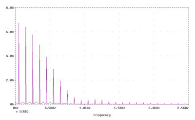
Figure 2: Frequency analysis of current in Figure 1
The benefit of this analysis is that the behaviour of electrical components is easiest to understand and define in terms of specific sinusoidal frequencies.
In this case, with a mains frequency of 50 Hz you can see that the harmonic currents up to orders of about 30, i.e. 1500 Hz, are quite significant. Beyond that they diminish quickly. The lower order harmonics of orders 3, 5, 7 and 9 are really high in amplitude and are not much less than the fundamental (50 Hz).
If the negative and positive half-cycles have the same shape then only the odd harmonics are present. In three-phase power circuits the triple-n harmonics (3, 6, 9, 12 etc.) are also absent, because they are cophasal, and cophasal currents are blocked in a three-wire circuit.
Strict definition and working definition for harmonics. Interharmonics.
A true harmonic can only have a frequency which is an exact integer multiple of the fundamental. Most simple non-linear devices such as rectifiers and iron-cored magnetic components generate true harmonic currents.
In modern power electronic circuits using active switching, which might not be synchronised with the supply frequency, new frequencies may be present which are not true harmonics. For example, as I illustrated in Blogs number 4 and 5 on Regenerative drives, an inverter operating with a switching frequency of 4 kHz with a 60 Hz supply generates currents at frequencies of 3880 Hz and 4120 Hz, as well as many others, which are not integer multiples of 60 Hz and therefore are not true harmonics. The correct term for these is Interharmonics. They are still unwanted frequencies and some of their effects are the same as for harmonics, so in general discussion they may be referred to simply as “harmonics”. This can cause confusion, so it is best to make clear whether we are talking about true harmonics or all kinds of distortion.
What effect do they have?
Referring to Figures 1 and 2 again, we have a rectifier connected to the mains supply. The supply is sinusoidal and has a single frequency of 50 Hz. The rectifier generates harmonic currents which flow in the supply. The rectifier is a source of current at the harmonic frequencies, which are emitted back into the supply and spread around the power system. Figure 3 illustrates this. The harmonic current is emitted by the load, and causes a harmonic voltage in the source impedance of the supply. The voltage is experienced by other power users connected to the same point of common coupling (PCC).
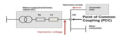
Figure 3: Propagation of harmonics in the power network
The harmonics have frequencies ranging from 100 Hz up to about 2500 Hz (we generally stop at about order 50, but some authorities look at 100 or even 200. The standard for harmonic measurements stops at 9 kHz). The first interesting point is that these are very low frequencies in the electromagnetic spectrum. This is illustrated in the spectrum shown in Figure 4;

Figure 4: Simplified electromagnetic spectrum showing position of power harmonics
“Radio frequency” is generally considered to begin at 9 kHz, and in fact there are very few radio applications below about 100 kHz because of the difficulty in generating a useful electromagnetic wave. This means that the harmonics are not propagated as waves and they only travel by conduction around the power system wiring. They do not cause interference by stray coupling, only by being conducted into other equipment through the power wires. The reason they have to be considered is that they are cumulative – so one rectifier in a TV set has a miniscule effect, but when millions of TV sets operate at the same time, their harmonics have the same frequency and phase so they add up in the power system. The overall effect is to distort the sinusoidal voltage waveform. Figure 5 illustrates the kind of “flat top” distortion caused by rectifiers;
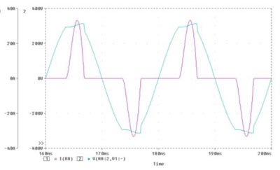
Figure 5: Voltage distortion caused by rectifier harmonics
A moderate level of harmonic current in the power system is of no concern, but if it becomes excessive then trouble can result. Some of the possible effects of excessive harmonics in the power system are listed below. All of these are quite unusual, but if they do occur they can be difficult and expensive to correct.
- Increased heating of some frequency-sensitive electrical equipment, especially:
- Capacitors for power-factor correction
- Induction motors
- Transformers
- Generators (e.g. small local generators such as backup power supplies)
- Acoustic noise in transformers, bus bars etc.
- Errors in equipment using the mains frequency for timing (now become uncommon)
- Unwanted triggering of UPS systems which respond to waveform distortion
- Noise pickup in analogue sound systems, e.g. theatre or church
- Unwanted tripping of power system protection relays, resulting in loss of the public supply
Serious difficulties with harmonics are unusual except in rather special cases. One example is a ship which has its own generator with limited power capability and a large number of drives or other rectifiers. However the power utilities do experience an accumulation of harmonics from the millions of small appliances in operation, and there are locations where the fifth harmonic on the public supply is at its limiting value.
“Noise”
Note that the effect of harmonics does not include the kind of disturbance to electronic circuits generally referred to as “electrical noise”, which tends to result in noise and vibration in analogue drive systems and/or data errors in digital data links. The reasons for this are:
- The frequency of the harmonics is too low for significant stray coupling by induction between adjacent electrical circuits. Most electrical interference is caused by much higher frequencies which can be coupled electromagnetically, or through the stray inductance of earth (ground) connections.
The harmonics are propagated as series-mode currents in the power circuit only, i.e. they travel in the power system power conductors and not in the earth (ground) connections. High frequency “noise” is usually in the common mode, i.e. it travels in conductors and the circuit is completed by the earth (ground). See Figure 6 for a further explanation;
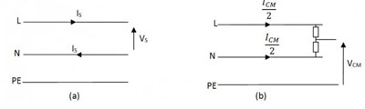
Figure 6: Series mode (a) and common mode (b) in a single phase power circuit
Harmonic data: input and output, voltage and current
Drive users sometimes request harmonic data for a drive. There is some possibility of confusion because they may refer to the input or the output, and to current or voltage. The table below summarises the data which is relevant to each place.
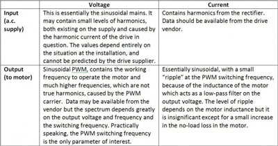
Sometimes a request for output harmonic data stems from a user’s prior experience with inverter drives of previous generations which used the quasi-square technique, and contained the non-triple-n harmonics of the working frequency. With PWM the harmonics are negligible.
To summarise the table, the only harmonic data which is a characteristic of a particular drive model is the input current data. That should be available from the supplier on request.
In part 2 of the harmonics blog we will look at how harmonics are measured and assessed, how they vary with drive loading, and what can be done if they need to be reduced.