The motor cable for a PWM variable speed drive can have some unexpected effects. In this Blog I look at some special considerations which are needed when choosing and installing a motor cable for a VSD.
Current rating
The steady-state loaded motor current is not appreciably changed by using a VSD with the motor. The motor current protection function in the drive is approved (e.g. by UL) for thermal protection of the motor and cable in the event of an overload. Therefore the basic current rating of the motor cable is the same as for a motor connected directly on line.
Cable sizing and voltage drop – cable sizing codes
Cable sizing codes used by electrical installers, including cable planning software packages, often have special provisions for motors. These would be based on a standard industrial induction motor started by direct connection to the power line (“Direct On Line” DOL starting). Long cables may need to be larger than would be dictated by the continuous full-load current rating, so as to restrict the voltage drop in the inductance and resistance of the cable during starting. A typical industrial induction motor draws a DOL starting current of about 5 times its maximum rated value, because of the high slip before it reaches its running speed; and during starting the available torque is not particularly high. It is possible for excessive voltage drop in the cable to result in the motor failing to start if the load torque is sustained at low speed.

When using a variable speed drive the motor slip is always low and the current during starting never exceeds the short-term rating (e.g. 110% or 150% depending on the application). Also, the drive can be tuned with the motor and its cable so that the cable voltage drop is compensated – at a speed below base speed there is voltage headroom available between the capability of the drive and the voltage required to achieve the working flux density in the motor. Therefore with a VSD there is no need to over-size the cable to reduce voltage drop at starting. In installations with long motor cable runs this fact can allow considerable savings in cable costs. When using cable-sizing software for planning an installation, the motor with VSD should be set as a simple resistive load, not a motor, in order to avoid the unnecessary allowance for motor starting current.
Types of cable – screening (shielding)
The VSD output uses Pulse Width Modulation (PWM) to create a supply with adjustable voltage and frequency to control the motor. The pulses have fast edges, with rise/fall times in the order of 100 ns. This means that the frequency content of the voltage in the motor and motor cable extends up to high radio frequencies – generally there is a very high level for frequencies up to around 10 MHz, and a considerable level up to around 50 MHz. In order to avoid electromagnetic interference (EMI) the cable needs to be screened so that emission of electromagnetic energy is suppressed. The presence of a grounded screen prevents electric field emission, and the correct connection of the screen at both the motor and inverter ends, using a bond with minimum self-inductance, prevents magnetic field emission. Both are necessary.
The possible emission from a wrongly managed motor cable can affect both radio frequency communications and nearby electronic equipment such as sensors and data circuits, which are sensitive to disturbances in these frequency ranges. The Electromagnetic Compatibility (EMC) standard for drives IEC 61800-3 (EN 61800-3) requires the motor cable to be screened, otherwise the drive output would have to be connected through a very expensive and unwieldy radio frequency filter device.
Practical tests have shown that cable screens using steel or copper can be equally effective provided they have good continuous coverage and continuity along the length of the cable. This facilitates radio frequency current flowing along the screen to cancel the magnetic field caused by the common-mode current in the power cores.

Grounding (earthing)
The motor ground connection is primarily to ensure safety in the event of a ground fault in the motor. The ground connection has to carry the fault current until the safety device (fuse or circuit breaker) interrupts the current, whilst ensuring that the touch voltage of the motor body remains within safe limits.
Normally the VSD limits the ground fault current to much lower levels and shorter durations than a fuse or circuit breaker. However it relies on complex semiconductor devices and circuits to achieve this, which might fail. For safety reasons therefore the ground loop impedance for the ground connection needs to be the same as if there were no VSD – ultimate protection is provided by the upstream protection device feeding the drive. The choice of ground conductor dimension is exactly the same as for a directly fed motor.

As explained above, the motor cable for a VSD needs to be screened. Whether this screen can also provide the safety ground connection depends on its impedance and on the code of practice used for grounding. It is common to use a separate copper ground conductor in order to avoid the need for a special calculation.
The question sometimes arises, whether to use a ground core within the screened motor cable (i.e. a 4-core cable) or an external one. From the point of view of safety, both solutions are equally good. For EMC reasons also, both methods can work, but care is needed with a 4-core cable. The ground core carries quite a high noise current, picked up from the power cores inside the cable. If it is taken to a point in the inverter wiring panel away from the cable screen termination, it will inject the noise current into the panel ground wiring, with a risk of disturbing signal circuits. It should be connected to the inverter panel physically very close to the screen termination.

Capacitance and inductance
The motor cable has natural self capacitance and inductance. At power frequencies the capacitance has negligible effect, whilst the inductance causes a small voltage drop which is mainly negligible except for very long cable runs and high DOL starting currents.
The effect on the fast-rising PWM pulses from an inverter is much more important. At every pulse edge the cable capacitance must be discharged. This results in quite large, but short, current pulses at every edge. These can cause high-frequency field emission, and also they form a load on the inverter power semiconductors during switching.
Fortunately the cable inductance is distributed along the cable with the capacitance, and has the effect of limiting the charging current. The net effect is described by the “Telegrapher’s equations” and results in cable parameters Z0, the characteristic impedance, and v, the propagation velocity.
At each PWM pulse edge, a current flows to charge the cable, given by:

Where ![]() = DC link voltage of inverter
= DC link voltage of inverter
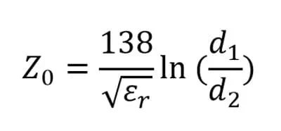
For a coaxial cable the characteristic impedance is given by:
Where:
![]() = relative permittivity of dielectric (insulator)
= relative permittivity of dielectric (insulator)
![]() = Inside diameter of outer conductor
= Inside diameter of outer conductor
![]() = Outside diameter of inner conductor
= Outside diameter of inner conductor
In a 3-phase screened cable the geometry is not a simple coaxial shape, but its behaviour is similar, the impedance being a function of the dielectric permittivity and the relative diameters of the inner and outer conductors. The geometry and dielectric material used in cables does not vary greatly, and the logarithmic term ![]() means that the impedance is not very sensitive to geometry changes. Measured values of
means that the impedance is not very sensitive to geometry changes. Measured values of ![]() for standard screened power cables range between about 45 ohm for 2.5 mm2 cable to 15 ohm for 120 mm2 cable. This means that for larger drives with current ratings over about 20A the charging current is insignificant, but for ratings below about 10A it has an impact and the drive has to be designed to supply the charging current without excessive power loss, or of unwanted over-current tripping.
for standard screened power cables range between about 45 ohm for 2.5 mm2 cable to 15 ohm for 120 mm2 cable. This means that for larger drives with current ratings over about 20A the charging current is insignificant, but for ratings below about 10A it has an impact and the drive has to be designed to supply the charging current without excessive power loss, or of unwanted over-current tripping.
The duration of the current pulse is determined by the length of the cable, it is equal to the time for the pulse to travel to the motor end and then return as an inverted reflection. The longer the cable the greater the effect on the inverter.
Some special cables can have abnormal values of ![]()
The ratio of diameters can be much reduced if there is no insulating jacket between the power cores and the screen, which may occur for highly flexible screened power cables. Mineral insulated copper clad cable (MICC) also has a low ratio of diameters, and the permittivity of the mineral insulator is high, so the impedance is very low.
Another situation where the effective ![]() will be low is if several cables are connected in parallel to achieve the required current rating, rather than use a single large-diameter cable. In these cases, unless the total cable length is very short it is often necessary to add series chokes between the drive and the cable to restrict the cable charging current. In Control Techniques we have occasionally encountered a case where the installer has used three cables in parallel and has used one cable with three cores for each phase. This arrangement is bad practice in any case because the mains frequency current in the phase cores induces counter-currents in the screens, which can result in heating of the screens. When used with a VSD it results in an exceptionally high stray current from the excessive capacitance between the power cores and ground, which can cause high-frequency interference with nearby circuits and also risks over-loading RFI filters through excessive common-mode (ground) current.
will be low is if several cables are connected in parallel to achieve the required current rating, rather than use a single large-diameter cable. In these cases, unless the total cable length is very short it is often necessary to add series chokes between the drive and the cable to restrict the cable charging current. In Control Techniques we have occasionally encountered a case where the installer has used three cables in parallel and has used one cable with three cores for each phase. This arrangement is bad practice in any case because the mains frequency current in the phase cores induces counter-currents in the screens, which can result in heating of the screens. When used with a VSD it results in an exceptionally high stray current from the excessive capacitance between the power cores and ground, which can cause high-frequency interference with nearby circuits and also risks over-loading RFI filters through excessive common-mode (ground) current.

In the above I have not particularly distinguished the modes in the cable to which the impedance applies. It is generally not necessary to consider this much detail, but the main modes which affect the drive are:
- Simple asymmetric mode, one core relative to all other cores and screen. This is relevant to drive loading but not to ground current or filter loading.
- Common mode, all power cores to screen and to ground core where fitted. This is relevant to ground current and filter loading.
Motor voltage overshoot and rate of change (dv/dt)
The cable capacitance and inductance causes voltage overshoots at the motor terminals at the pulse edges. In terms of the Telegrapher’s equations, these can be understood as reflections at the motor terminals caused by the mismatch of impedance. Even quite short cables result in some overshoot. This can be surprising if you are unfamiliar with inverters and fast-changing pulses – on a microsecond timescale the voltage at the motor is quite different from that at the inverter even though they are connected together.
Motors have a voltage withstand capability which depends on the voltage rise-time. For rise-times below about 0.8 microseconds the voltage withstand may be reduced because the voltage tends to be concentrated into the first turns of the winding, and stresses the interturn insulation. Most motors are designed for use with inverter drives running from a 400 V or 480 V supply without special measures. For 690 V motors it is strongly recommended to use a purpose-designed inverter-rated motor to avoid any risk of premature insulation failure. Such motors should be specified in compliance with the guidance given in IEC document TS 60034-25 (“Guidance for the design and performance of a.c. motors specifically designed for converter supply”).
Multiple motors
Occasionally it is desirable to operate a number of motors from a single drive. For example, small ventilation fans may be fitted around a building and driven from a single drive, each with its own cable. In this situation the capacitance of the cable is dictated by its total length, but the inductances of the sections appear in parallel to the drive, not in series. For n cables the impedance seen by the drive at its pulse edges is cap15
A series choke should be used in this case to restrict the capacitance charging pulses, otherwise the drive is likely to suffer from premature over-current tripping or limiting caused by the high charging current.