In this article Jacques Saint-Michel, scientific director for Leroy-Somer, delves into optimal control theories for permanent magnet motors.
The behaviour of permanent magnet motors can be represented by the single phase vector diagram hereunder. For generality purpose, armature reaction is supposed to be anisotropic, according to the 2 axis theory.

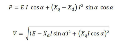
The main control parameter is the angle a between stator current and EMF. For simplicity, one generally can neglect the stator resistance and leakage reactance, so that the power per phase and the line voltage can be expressed as:
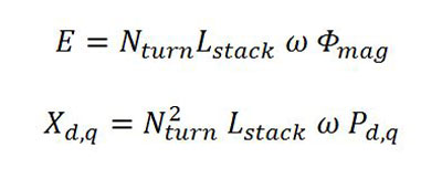
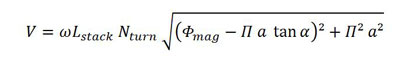
Introducing the effective number of turns, the stack length, the magnet flux and the respective permeance of axes, EMF and reactances can be expressed as:
Consequently, power and voltage can be alternatively written as follows, where AT are the amp-turns:
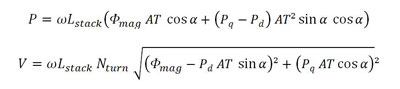
Obviously enough, amp-turns are the most relevant parameter for the following discussion.
Case of isotropic machines
This can for instance be the case for surface mounted magnets, but also for radial magnets mounted in flux concentration, like in HPM motors.
In this situation, the 2 permeance are equal to, and writings can be simplified:
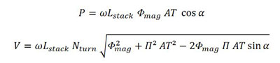
For given machine size, the power will be constant if is constant. Let a be this quantity. Then:
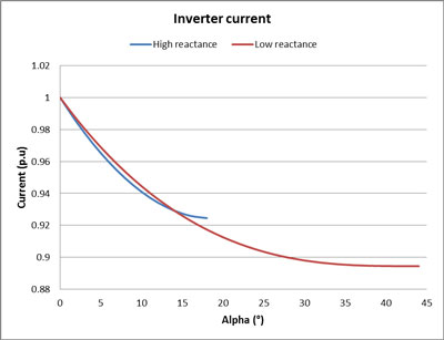
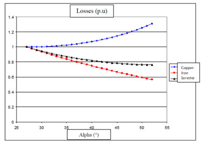
Of course, copper losses of the motor will increase, due to more turns and in spite of lower current, but in the same time motor core losses decrease (less flux) and inverter losses decrease as well (less current).
In other words, both inverter size and total efficiency can be optimized.
So, the traditional “zero angle” strategy for isotropic machines is not necessarily optimal, if the motor and the drive are mutually optimized, taking into consideration the motor winding definition.
Case of non-isotropic machines
This is the case, for instance, of permanent magnet assisted synchronous reluctance machines.
Here, the saliency is intentionally made high, in order to get strong reluctance torque, in addition to magnet torque.
This topology allows either to get very high specific torque with rare earth magnets, or high specific torque with low cost magnets (ferrite for instance, or plastic bonded magnets).
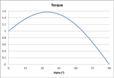
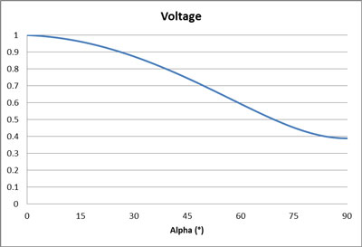
Typical torque and voltage capability curves are shown hereunder.
The same kind of procedure as previously can of course be conducted, but equations are a little bit more complicated.
For this reason, they are not shown here.
We just show how losses (hereunder individually in per-unit) can be impacted with optimized number of turns, together with optimized current angle (around 27° initially with non-optimized winding).
This motor topology is even more subject to optimization than traditional motors, due to increased degrees of freedom brought by saliency.
Again, a very nice global optimization of the power drive system can be achieved.