
Motor Replacements and Parts
- Where do I find parts for my HVAC or General Purpose Fractional Horsepower motor?
A: Available parts can be sourced through EIS/Holden (800-367-1212) using the motor identification number.
- Where do I find parts for my Pool/Spa motor?
A: Available parts can be sourced through EIS/Holden (800-367-1212) or Parts Company of America (800-323-0620) using the motor identification number.
- Where can I get a replacement motor? I cannot find it in your replacement motor catalog.
A: Your replacement options may depend on the motor's use. Some units are produced for OEMs and their specific application. They are your primary replacement source if no catalog equivalent is listed. Our HVAC wholesalers and industrial distributors can advise you on other options if the OEM can no longer provide a replacement. A physical inspection of the motor may be required. Homeowners wishing to replace motors in their heating or air conditioning units should contact their local HVAC contractor for assistance.
- Who do I contact regarding service for my motor?
A: Your local EASA shop can advise on service options. If your motor is less than a year old, you should take it and your receipt back to the point of purchase for a warranty replacement.
For U.S. MOTORS® brand Integral Horsepower ratings, the support section of this site provides links to authorized service stations and other contacts for service and warranty issues.
- Where do I find parts for my U.S. MOTORS® brand Integral Horsepower product?
A: Any of the distributors listed on the distributor search can assist you with identifying and ordering parts.
- Where do I find a wiring diagram for my motor?
A: Online wiring diagrams are only available for current catalog products in our eCatalog. For additional ratings, you will need to send us a request for the diagram. Be sure to include the id number off of the motor nameplate.
Technical Service Questions
- What types of accessory leads can be found on U.S. MOTORS® brand products?
A: Accessory leads used include space heaters, bearing detectors, and winding detectors. Refer to details on winding temperature protections for brief descriptions of some of these.
- Is it possible to connect a multi-lead motor across the line? If so, what is the procedure for doing this?
A: Yes, this is possible. In order to connect a multi-lead motor across the line, you must use the “RUN” connection for the appropriate voltage on the connection plate. For example, the diagram below shows the “RUN” connection as Full Winding connection. Motor leads T1 & T7 are combined and connected to line 1. Leads T2 & T8 are combined and connected to line 2. Leads T3 & T9 are combined and connected to line 3. Refer to the following diagram and table for further information.
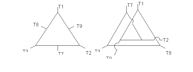
Table 4
Voltage
L1
L2
L3
OPEN
Full Winding
(T1, T7)
(T2, T8)
(T3, T9)
---------
Part Winding
T1
T2
T3
(T7) (T8) (T9)
Note: To reverse the direction of rotation, interchange connections L1 and L2.
Each lead may have one or more cables comprising that lead. In such case, each cable will be marked with the appropriate lead number.
- After disassembling and reassembling a motor, what is the proper method for adjusting the rotor end play?
A: Should a motor be disassembled for any reason, the rotor end play must be adjusted. Use one of the following procedures, depending upon the type of thrust bearing:
1. Spherical Roller Thrust Bearings and Angular Contact Bearings (With Springs)
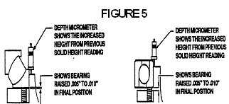
On spherical roller or angular contact thrust bearings with springs, setting the correct end play for preload requires a controlled assembly method, due to various deflections internal to the motor and friction of locknut threads from spring force. An end play setting of .005 to .008 inches is required to allow the lower guide bearing to return to an unload position when external thrust is applied to the motor (see Figure 5). End play can be properly adjusted by the following recommended procedure:
-
Place spring retainer, without springs and lower thrust washer of bearing, into upper bracket bearing bore.
- Using a depth micrometer, measure the distance between the top of the lower thrust washer and the faced surface on top of the bearing housing. Record this dimension to three decimal places.
- Add .005 and .008 inches to the recorded dimension to obtain the correct minimum and maximum settings range for the unit.
- Reassemble bearing with springs; motor is now ready to set end play.
NOTE: Certain motor builds require removal of the fabricated steel or cast aluminum oil baffle to provide access for depth micrometer measurements.
Motors built with spherical roller thrust or angular contact bearings with springs require a minimum external thrust load, sufficient to compress upper die springs and unload lower guide bearing from axial spring thrust. Refer to the motor’s spring thrust plate for required minimum thrust.
NOTE: Do not run motor without load for more than fifteen minutes, as lower bearing damage may occur and improper seating of thrust bearing may cause vibration.
2. Angular Contact Ball Bearings (Without Springs)
No preliminary measurements are required to set end play. End play may be set by any of the following methods described in this section.
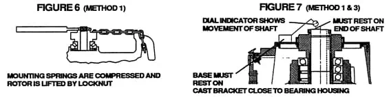
- To correctly adjust the rotor end play setting on units with angular contact ball bearings, a dial indicator should be positioned to read the shaft axial movement. (See figure 7 for location of dial indicator.) The rotor adjusting locknut should be turned until no further upward movement of the shaft is indicated. The locknut is then loosened until .005 to .008 end play is obtained, lock the locknut with the lockwasher.
- Motors that have two opposed angular contact bearings, locked on the mount for up and down thrust, do not require rotor end play adjustment. The shaft, however, must be set to original “AH” (shaft extension) to prevent the guide bearing in the lower bracket from taking external thrust.
End Play Adjustment Methods
Method 1 (refer to Figures 6 & 7)
This method requires the user to install a bolted chain from the bearing mount back to a lifting lug, and rotate the locknut with a spanner wrench and 8 foot long bar until the dial indicator shows no movement on the end of the shaft. The locknut should then be loosened until .005 to .008 end play is obtained. Lock the locknut with the lockwasher. (See figure 7 for location of dial indicator.)
NOTE: This is the lowest cost of the three methods and requires the least amount of equipment. This method, however, may be less desirable than Method 2, as considerable locknut torque may be encountered on units with die springs.
Special equipment required includes:
-
Locking bolts
-
3/4” chain
-
Spanner wrench with extension
-
Dial indicator
-
Depth micrometer
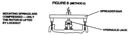
Method 2 (refer to Figure 8 - Utilized on Spring Loaded Bearings Only)
This method utilizes a spreader bar and chains to wrap around lifting lugs, a hydraulic jack (five ton), and a crane to lift the spreader bar. The hydraulic jack is supported by two steel blocks of equal thickness on top of the bearing mounting, with the jack pushing against the spreader bar. On very heavy solid shaft rotors, the rotor can be lifted by placing a second jack below the motor to allow the locknut to be turned easily. After correct range (recorded earlier) is obtained, lock the locknut with the lock washer.
NOTE: This method utilizes usual shop equipment and tools. End play settings can be checked quickly on larger vertical motor products. The locknut lifts rotor weight only.
Special equipment required includes:
-
Large spreader bar with chains and locking bolts
-
Overhead crane
-
Spanner wrench
-
Hydraulic jack (five ton)
-
Depth micrometer
-
Metal blocks
-
Dial indicator
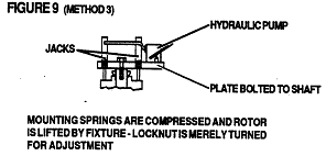
Method 3 (refer to Figure 9)
This method uses a one inch thick steel disc, with center hole for shaft end bolt, and two threaded hydraulic jacks connected to a single pump. Apply load to the hydraulic jack until the dial indicator shows no movement on the end of the shaft. (See figure 7 for location of dial indicator.) Pressure from the hydraulic jack should be relieved until .005 to .008 end play is obtained. Lock the locknut with the lock washer.
CAUTION - Excessive hydraulic pressure should not be used when setting end play, or bearing damage may occur.
NOTE: This method is directly usable on solid shaft motors, and can be utilized on some HOLLOSHAFT® motors with the use of a long threaded rod and plate. It is very easy to apply and settings can be checked quickly, especially in field service. The locknut does not see rotor weight or spring force and can be turned easily.
Special equipment required includes:
-
Fixture with hydraulic jacks (five ton)
-
Dial indicator or depth micrometer
-
Spanner wrench
CAUTION: After setting end play by any of the above methods, run unit for fifteen minutes and recheck end play setting. If not within range, end play must be reset. All loosened or removed parts must be reassembled and tightened to original specifications. Keep all tools, chains, equipment, etc. clear of unit before energizing motor.
3. NEMA Frame Verticals with Thrust Bearing in Lower Housing
End-play setting on NEMA frame vertical motors with the thrust bearing at the lower end of the motor is accomplished by the use of shims on the outboard side of the upper guide bearing. The endplay should be determined before disassembly by using a dial indicator on the end of the shaft. After repairs are completed, the motor should be reassembled and with the original shims. The end play should be checked to insure the original setting remains. If unable to determine original endplay due to damage or other reasons, contact Product Service for values.
-
- What do you recommend as alarm and shut-down temperature settings for winding RTD's?A: The following tables (Tables 1 and 2) show alarm and shut-down temperatures based on the motor service factor, HP rating, and class of temperature rise. These temperatures apply to both winding RTD’s and thermocouples. See winding temperature detectors section for alarm / shut-down temperatures of thermostats and thermistors.
Table 1: Monitors With Alarm and Shutdown
TEMPERATURE IN ° C
Insulation
CLASS A
CLASS B
CLASS F
Rating
Alarm
Trip
Alarm
Trip
Alarm
Trip
1.0SF<1500HP
110
120
130
140
140
150
1.0SF>1500HP
105
115
125
135
140
150
1.15SF<1500HP
120
130
140
150
160
165
1.15SF>1500HP
115
125
135
145
160
165
Table 2: Monitors With Shutdown Only
INSULATION
TEMPERATURE IN ° C
RATING
CLASS A
CLASS B
CLASS F
1.0SF<1500HP
110
130
140
1.0SF>1500HP
105
125
140
1.15SF<1500HP
120
140
160
1.15SF>1500HP
115
135
160
- The bearings on my unit are too hot to touch, and I am worried there may be a problem. What is a normal/safe bearing temperature?
A: It is not abnormal for bearings to be “too hot to touch.” Following is a list of standard temperatures for both mineral-oil-lubricated and synthetic-oil-lubricated bearings.
Mineral-oil-lubricated bearings:
- alarm temperature: 95° centigrade
- shutdown temperature: 100° centigrade
Synthetic-oil-lubricated bearings:
- alarm temperature: 110° centigrade
- shutdown temperature: 115° centigrade
These temperatures apply to grease-lubricated as well as oil-lubricated bearings. In addition, new bearings often require a break-in period of up to 100 hours. During this time, temperatures and noise levels can be slightly elevated. However, these levels should decrease somewhat after this break-in period.
- What types of bearings are most frequently used on U.S. MOTORS® brand products?
A: We most frequently use anti-friction / rolling element bearings. These bearings are characterized by rolling elements which separate the stationary part from the rotating part. Specific types of these bearings include:
- Deep Groove (Conrad) Ball Bearings
- CARB Toroidal Roller Bearing
- Double Row Angular Ball Bearings
- Cylindrical Roller Bearings
- Spherical Roller Radial Bearings
- Angular Contact Ball Bearings
- Spherical Roller Thrust Bearings
Following is a brief description of each bearing type listed:
Deep Groove (Conrad) Ball Bearings
Typical bearing manufacturing series numbers used range from 6200 to 6400.
Deep groove ball bearings are available in open type bearings, shielded bearings (single or double), and sealed bearings. Open type conrad bearings, which are supplied on explosion proof 180 frames and higher and ODP/TEFC 400 frames and higher, require bearing caps to contain grease in the housing. Shielded bearings, supplied on all 140 frames (ODP/TEFC through 360 frame and on all automotive duty), can be used on motors without bearing caps. Sealed bearings, which are “lubed for life”, possess a reduced speed limit due to seal friction. These sealed bearings are supplied for customer specials only.
Double Row Angular Ball Bearings
Deep groove ball bearings are the most common type of bearing for electrical motor use. These bearings are good for moderate radial and axial loads. They are used in vertical high thrust motors as a guide bearing for momentary upthrust.
Typical bearing manufacturing series numbers used range from 5200 to 5400.
Double row angular ball bearings are very similar to single row conrad bearings, with the addition of an extra row of balls. Because of this addition, these double row bearings can handle larger radial and axial loads than conrad bearings. Double row angular ball bearings, available open, shielded, or sealed, are provided on both horizontal and vertical close-coupled pumps, and on larger normal thrust motors as thrust bearings. Sizes larger than 5316 are not readily available.
Cylindrical Roller Bearings
Typical bearing manufacturing series numbers used are preceded by an “N”. For example: N2XX or NU2XX.
Cylindrical roller bearings are used on horizontal motors where high radial loads are present. Although equivalent in size to conrad ball bearings, cylindrical bearings have a lower speed limit and are only available as open type bearings. These bearings are not available for direct connected motors, and are provided upon special order only on motors with an overhung load.
Spherical Roller Radial Bearings
Typical bearing manufacturing series numbers used range from 22,000 to 24,500.
Spherical roller radial bearings are used on horizontal motors which possess an extremely high radial load, or on motors which require an extended bearing life. Typically, these bearings are wider than conrad ball bearings, thus. making special engineering more difficult. In addition, they have a lower speed limit than cylindrical roller bearings. Spherical roller radial bearings can not withstand axial loading.
Angular Contact Ball Bearings
Typical bearing manufacturing series numbers used range from 7200 to 7400.
Angular contact ball bearings are supplied on vertical motors only. High thrust vertical motors using single angular contact bearings are capable of continuous thrust in only one direction. Multiple angular contact ball bearings can be mounted either back-to-back for up/down thrust, or in tandem sets of two or more bearings for extra high thrust loading.
Spherical Roller Thrust Bearings
Typical bearing manufacturing series numbers used range from 29,300 to 29,400.
Spherical roller thrust bearings are supplied on vertical motors only. These bearings can support extremely high thrust loads (up to 300% of standard thrust capacity) and moderate radial loads. Preload springs are required to supply minimum downthrust to bearings at start up in order to prevent bearing skidding. In addition, the motor requires minimum downthrust at all times to compress preload springs and unload the lower guide bearing for maximum life. Water cooling is generally required.
- How do you determine a machine's vibration?
A: The criteria utilized to determine bearing housing vibration is the peak value of the unfiltered vibration velocity in inches per second. The greatest value measured at the set measuring points identifies the vibration of the machine.
- After requesting a motor equipped with class "F" insulation, I received a unit on which the insulation class is labeled "B". Was there a mix-up in my order?
A: No, there was not a mix-up. We build all of our motors with class “F” insulation or better. When the nameplate indicates class “B”, this means the motor is designed to operate within class “B” temperature rise limits. These limits are 80 degrees centigrade at 1.0 service factor, and 90 degrees centigrade at 1.15 service factor. For many years, it has been our policy to nameplate open dripproof motors that meet this temperature rise criteria with the insulation class “B”, regardless of the actual insulation type. This gives the end user the information that the motor has a 90 degrees centigrade, or less, temperature rise at 1.15 service factor.
- What driver technologies are available for variable speed applications?To find out more, please read Driver Technology for Variable Speed Applications.
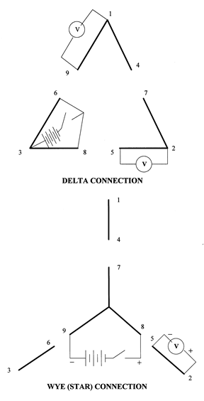
- I have lost track of the leads of a nine lead three phase motor. How can I re-identify these leads?
A: For the purpose of this test, a lantern battery of six or nine volts works best. Use a DC volt-ohm meter with a 20K ohms per volt DC scale. Battery and voltmeter leads should be properly identified. Alligator clips should be used on both. The motor must be completely assembled. Test the nine leads for continuity with the ohmmeter to determine whether the motor is star (wye) or delta connected. The delta connected motor will possess three sets of three leads with continuity between them. On the other hand, the star connected motor will have only one set of three leads with continuity between them, and three sets of two leads with continuity. Following are specific steps to take when identifying leads of both a star connected and a delta connected motor.
Delta Connected Motor:
Using an ohmmeter, identify the three groups of three leads. Separate these groups by tying them with tape. Attach leads to a pair of wires in a group, and observe the voltage drop from each pair of energized leads to the third lead in that group. Continue until a combination is found that gives a voltage drop from each of the energized leads to the third lead equal to one half of the battery voltage. The lead located halfway between the other two will thus be the corner lead of the delta. Repeat this for each group of leads, marking the corner leads #1, #2, and #3.
Next, use the inductive kick test method to identify the proper markings for the other two leads of each group. The two coils #3 & #6 and 3 & #8, acting in parallel, will produce the effect of a coil positioned halfway between the actual position of the two coils. The flux produced by #3 & #6 and #3 & #8 combined, will be perpendicular to the axis of #1 & #4 and #2 & #7. Opening and closing a switch in this circuit will produce a kick in coils #1 & #9 and #2 & #5, but no kick in #1 & #4 and #2 & #7.
Therefore, if the battery is connected from #3 & #6 and #3 & #8 as shown, opening and closing the battery circuit, the voltmeter will identify leads #1, #4, and #9 and can be distinguished by noting the magnitude rather than the polarity. The voltmeter can then be connected to terminal #2 for determination of the leads #5 & #7. Leads #2 to #7 will give little or no deflection, and leads #2 to #5 will give a substantial deflection.
In succession, the battery is then transferred to the corner of #1. Tie the battery between leads #1 & #4 & #9. Making and breaking the circuit will be perpendicular to #3 & #8 and #2 & #5, resulting in no deflection. However, there will be a deflection from leads #2 & #7 and #3 & #6. Placing the battery next on the #2 & #5 and #2 & #7 leads will be perpendicular to #1 & #9 and #3 & #6 leads, therefore creating no deflection. Leads #1 & #4 and #3 & #8 would then have a deflection, thus concluding the lead testing of the nine lead delta connected motor.
Star Connected Motor:
Mark the three leads with continuity, #7, #8, and #9. Clip the battery to the #8 & #9 pair, clipping onto one and flashing the other. Clip the voltmeter to each pair of leads with continuity between them, until a pair is found that produces little to no “kick” or deflection. This pair of leads consists of the #1 & #4 leads. Next, move the battery to the #7 & #8 combination, with the positive lead on the #7 lead and the negative lead to be used for flashing the #8 lead. The voltmeter is so placed on the #1 & #4 pair that an upscale deflection is observed on the “make” of the negative #8 lead. The voltmeter positive lead is then the #1 motor lead, and the negative voltmeter is the #4 motor lead.
Next, move the battery to #7 & #9 leads with the positive lead on the #9 motor lead, and the negative to flash the #7 lead. Identification of the #3 motor lead is then determined by an upscale kick. The positive voltmeter lead should be on this lead, and the negative lead should be on the #6 motor lead. Shift the battery to the #8 & #9 pair, with the positive battery lead on the #8 lead and the negative used for the flashing. An upscale kick will identify the #2 motor lead. The positive voltmeter lead will be found on the #2 lead, and the negative voltmeter lead will be the #5 lead. This concludes the lead testing of the nine lead star connected motor.
- What is the purpose of bearing insulation?
A: Bearing insulation is required to prevent circulating rotor currents which can damage bearings. Our practice is to insulate the non-drive end shaft bearing journal with a ceramic (aluminum oxide) or Belzona #1111 coating. Insulated sleeve bearings are purchased with the outer diameter insulated by the bearing manufacturer. Insulated bearings are provided as standard on the following TITAN® products:
- All 6-pole motors
- Vertical motors 5800 frame and larger
- Horizontal motors 6800 frame and larger
- Motors for inverter duty applications
- Sleeve bearing motors
Any product by customer request - TITAN® or NEMA size (at additional cost to customer).
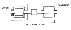
- Is it necessary to insulate both the drive end and the non-drive end bearings in order to eliminate circulating currents?
A: In the diagram below, arrows represent the direction of current flow through the rotor and motor frame. Insulating either bearing is sufficient for elimination of circulating currents, so long as the motor is not attached to driven equipment.
;
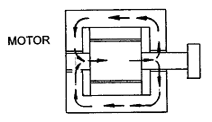
If only the drive end bearing is insulated and the motor is connected to driven equipment via a conductive base and coupling, circulating currents can still cause bearing damage by including the driven equipment in the circuit. An insulated base or coupling would also be required to break the circuit.
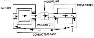
Common practice is to insulate only the non-drive end bearing. This is sufficient to eliminate any current flow.
- Is there a specific procedure to follow when insulating bearings? If so, what is this procedure?
A: Following are some guidelines to follow when insulating bearings. Apply sufficient alumina oxide coating to allow for finished grinding to original bearing journal dimensions with a 63 RMS, or better, surface finish. A phenolic sealer must be applied after the initial machining, but before the finish grind.
Suggested insulation materials:
- * Alumina oxide (Metaceram® 25010 or equivalent) - P/N 936521.
- * Bonding material (Metaceram® 21021 or equivalent) - P/N 936520
- + Sealer (Metcoseal® AP from “Metco”) - P/N 936557.
OR
BELZONA® 1111 (Super Metal)
Vendors:
*for Metaceram® materials:
Eutectic Castolin TD 3000 Torch Downers Grove, IL (800) 323-4845
+for Metcoseal® sealer:
Metco Seal (800) 826-3826
For Belzona:
BELZONA , INC. 2088 N.W. COURT MIAMI, FL 33172 WWW.BELZONA.COM - Please explain the limits of bearing housing vibration.
A: The following limits of vibration pertain to uncoupled, resiliently mounted machines, running at no load. For machines tested with rigid mounting, the values given should be multiplied by 0.8. Vibration levels given here refer to internally excited vibration only. Motors as installed (in situ) may exhibit higher levels.
Figures 10a and 10b, taken from NEMA MG1-7.08, show limits for bearing housing vibration levels of machines resiliently mounted for both unfiltered and filtered measurements.
For unfiltered vibration, the measured velocity level shall not exceed the limit for the appropriate curve in figure 10a corresponding to the rotational frequency. For filtered vibration, the velocity level at each component frequency of the spectrum analysis shall not exceed the value for the appropriate curve in figure 10a at that frequency.
Figure 10: Machine Vibration Limits
Figure 10a
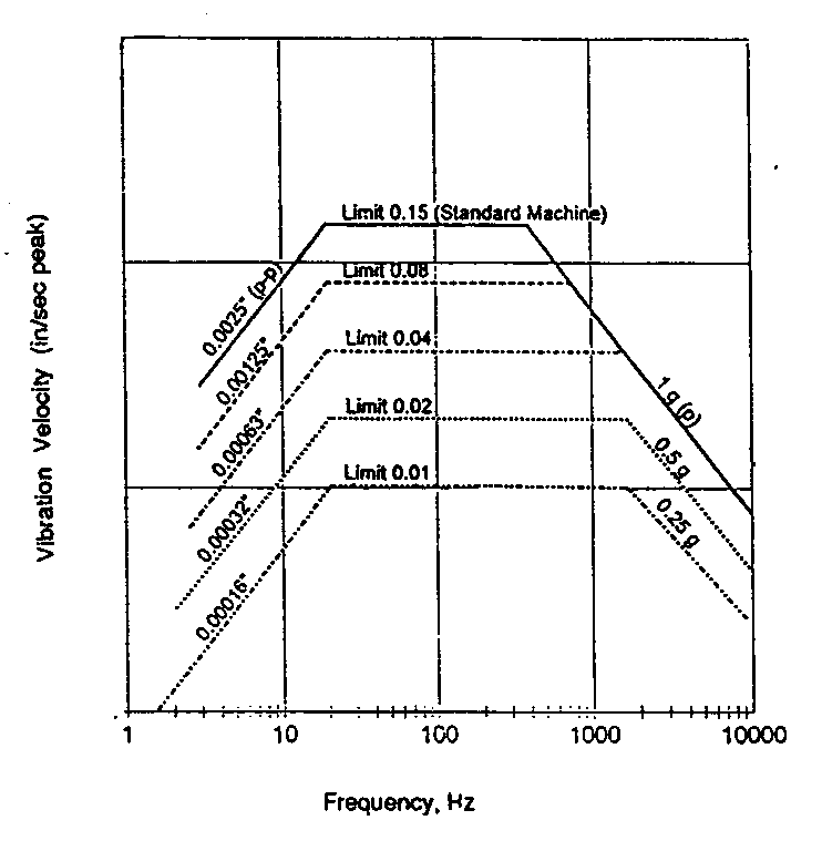
Figure 10b
Vibration
LimitMachine Type - General Examples
0.15
Standard industrial motors; motors for commercial or residential use
0.08
Machine tool motors; medium/large motors with special requirements
0.04
Grinding wheel motors; small motors with special requirements
0.02
Precision spindle and grinder motors
0.01
Precision motors with special requirements
- How can motors in service be re-lubricated?
A: Units are pre-lubricated at the factory and do not require initial lubrication. Re-lubricating interval depends upon speed, type of bearing and service. Refer to table in the Operating and Instruction Manual provided with motor for suggested re-greasing intervals and recommended greases. Operating conditions may dictate more frequent lubrication. Motor must be at rest and electrical controls should be locked open to prevent energizing while motor is being serviced (refer to section on Safety). If motor is being taken out of storage, refer to storage procedures.
To re-lubricate bearings, remove the drain plug. Inspect grease drain and remove any blockage with a mechanical probe taking care not to damage bearing. Under no circumstances should a mechanical probe be used while the motor is in operation. Add new grease at the grease inlet. New grease must be compatible with grease already in the motor (refer to Table 1 in Operating & Maintenance Manual for replenishment quantities). Run the motor for 15 to 30 minutes with the drain plug removed to allow purging of any excess grease. Shut off unit and replace the drain plug. Return motor to service.
CAUTION
Over greasing can cause excessive bearing temperatures, premature lubricant breakdown and bearing failure. Care should be exercised against over greasing.
CAUTION
Greases of different bases (lithium, polyurea, clay, etc.) may not be compatible when mixed. Mixing such greases can result in reduced lubricant life and premature bearing failure. Prevent such intermixing by disassembling the motor, removing all old grease from bearings and housings (including all grease fill and drain holes). Inspect and replace damaged bearings. Fill bearing housings and bearing approximately 30% full of new grease. Remove any excess grease extending beyond the edges of the bearing races and retainers. Refer to Table 2 in Operating & Maintenance Manual for recommended greases.
- Does a machine's mounting style affect its vibration?
A: Yes. When evaluating the vibration of electrical machines, it is important to understand the machine’s mounting because mounting and vibration are closely linked. Two passive (admit insignificant external disturbances to the machine) methods of mounting a motor are resilient mounting and rigid mounting. Following is a brief description of each, and an explanation of their affect on vibration.
Resilient Mounting: Resilient mounting entails suspending the machine on a spring, or mounting it on some type of elastic support (rubber, springs, etc.). Natural oscillation frequencies of the suspension system and machine should be less than 25 percent of the frequency corresponding to the lowest speed of the machine under test. The effective mass of the elastic support should be no greater than 10 percent of that of the machine, in order to reduce the influence of the mass and the moments of inertia of these parts on the vibration level.
Rigid Mounting: Rigid mounting entails fastening the machine directly to a relatively massive foundation. According to NEMA MG1-7.06, a relatively massive foundation is one that has a vibration which is limited, during testing, to 0.02 in/s peak (0.5 mm/s peak) above any background vibrations. The horizontal and vertical natural frequencies of the complete test arrangement shall not coincide within +10 percent of the rotational frequency of the machine, within +5 percent of two times the rotational frequency, or within +5 percent of one- and two- times the electrical-line frequency.
- After storing my motor for an extended period of time, I am now ready to install it. Is there any specific inspection procedure that must be followed?
A: Yes. Following storage, an extensive inspection must be performed on a motor by one of our authorized service stations. This inspection must include the following elements:
-
Render an external inspection of the motor to assure the unit is clean, ventilation openings are free of obstructions, and no damage has occurred.
-
Perform a megger test of motor windings to insure satisfactory insulation resistance.
-
Rotate the shaft to check for roughness in bearings or interference between rotating and stationary parts.
-
Perform a bench test on the unit to check for excessive amp. draw, noise, or vibration.
-
Regrease the motor bearings (as applicable) in accordance with the unit’s operating instruction folder.
-
The authorized service station must install a plate/tag indicating the date of inspection. Make any corrections which inspection shows to be needed.
-
- How does the motor insulation system class relate to the winding temperature rise?
A: Table 3 gives average winding temperature rises for various motors. Frame surface temperatures are typically 15 - 20 degrees centigrade less than the average winding temperature, depending on the size and type of motor along with standard manufacturing variation. For example, a motor designated class F with a 1.15 service factor has an allowable average winding temperature rise of 115 degrees centigrade. This motor has a total temperature of 155 degrees centigrade with the inclusion of the 40 degrees centigrade maximum allowable ambient temperature. Therefore, this motor frame surface temperature could reach 135 - 140 degrees centigrade, as affected by ambient and load conditions.
Table 3: Average Winding Temperature Rise
(Based on maximum ambient temperature of 40°C; Temperatures given in Degrees C)
Insulation Class
A
B
F
H
Motors with 1.0 service factor other than those listed below
60
80
105
125
All motors with 1.15 or higher service factor
70
90
115
-----
Totally-enclosed non-ventilated motors with 1.0 service factor
65
85
110
130
Motors with encapsulated windings and with 1.0 service factor, all enclosures
65
85
110
-----
- How do I go about obtaining parts for old U.S. MOTORS® brand motors, or motors still under warranty?
A: In order to obtain parts for your old U.S. MOTORS® brand motors, or those still under warranty, you must contact one of our distributors.
- What causes the lubricating oil in my vertical motor to foam?
A: Oil foaming is generally caused from moisture contamination, cleaning solvents etc. that get into the oil. The contaminants tend to discolor the oil giving it a milky appearance and the bubbles will dissipate very slowly after the motor has stopped.
The primary method of correcting foaming is to have the oil reservoir and associated parts thoroughly steam cleaned and baked dry. The main emphasis is to make sure all contaminates have been removed and the reservoir is completely free of moisture. If the issue still persists, anti-foaming agents are available as an additive to stop the foaming.
- My motor has a connection plate which says Dual Voltage Wye Start, Delta Run with PWS on the Low Voltage. How should I hook it up?
A: This motor has very good versatility and may be used in several power supply applications. It is a dual voltage machine and may be used on either voltage as defined on the connection plate. It is designed for use on a Wye Start, Delta Run starter. This is a special motor contactor which starts the motor on its Wye connection to limit the inrush and then switches to Delta for running. The motor must not be run on the Wye connection for more than 30 seconds as severe winding damage may occur. This motor may also be started across the line and run on the Delta connection.
In addition, the motor may be used on the low voltage connection as a part-winding start motor, also to limit the inrush required. After a brief period, it is switched to the full winding.
- What is the procedure to follow when changing the direction of rotation on TEFC motors?
A: U.S. MOTORS® brand TEFC motors are equipped with one of three types of external cooling fans:
- Propeller type (most two pole and some smaller motors)
- Sirocco type (most four pole motors)
- Radial type (some two and four pole motors; all six pole and slower motors)
Radial type fans are bi-directional. However, propeller and sirocco types are uni-directional. Although changing the rotational direction of a motor equipped with a propeller type requires a different fan, the sirocco type can be reversed in the field by performing the following steps:
-
Remove the fan cover guard in order to gain access to the fan.
-
Remove the fan from the shaft. This may require heating the fan hub to expand it loose from the shaft.
-
Remove the “baffle plate” from the fan casting and mount it on the opposite side. This will require drilling and tapping new mounting holes (use the “baffle plate” as a template).
-
Re-balance the reworked fan assembly.
-
Install the fan back onto the shaft with the “baffle plate” toward the motor.
-
Reinstall the fan cover guard.
-
Remove any direction of rotation arrow(s), turn 180 degrees and reinstall.
-
Reverse the leads if required to obtain the desired direction of rotation.
NOTE: Be sure the power is off and steps are taken to prevent accidental restarting of the motor before attempting to do any of the above procedures.
- Whom should I contact in order to obtain rewind data for a particular motor?
A: If you are one of our authorized service shops, you can obtain rewind data by contacting our Southaven distribution center at 662-342-7373. However, if you are not an authorized service shop, you must contact a distributor in order to obtain this information.
- Is there a specific procedure which should be followed when rewinding U.S. MOTORS® brand inverter duty motors? If so, could you please explain it.
A: Following are guidelines to use when rewinding U.S. MOTORS® brand inverter duty motors:
-
Use inverter grade magnet wire. If not available, triple build wire may substitute.
-
Avoid loose windings - use slot fillers as required.
-
Insulate between phases, center of each coil group, both end turns and in slots.
-
Secure end turns - tie or band both winding ends.
-
Be especially careful to avoid damaging winding magnet wire.
-
Recommend two cycles of VPI treatment for all rewinds.
-
- What is the importance of a space heater and what affect does it have on warranty?
A: Electric motors frequently have space heaters installed, at the customer’s request, to prevent moisture condensation in the motor when it is not running. In applications where the possibility of condensation is not a factor, or where continuous operation of the motor prevents the formation of condensation, space heaters are not necessary.
Our warranty policy covers manufacturing defects, and allows for repair or replacement to remedy any situations which may arise within the warrantable period. The failure of a motor due to condensation does not fall into this category and is, therefore, not considered for warranty coverage. If the project plans and specifications do not require space heaters, then the space heaters present in the unit may be left unconnected and the space heater warranty nameplate may be removed. However, as previously stated, motor failure due to condensation is not warrantable.
- Why are there minimum external down thrust requirements for motors built with spring loaded thrust bearings? What are these requirements?
A: Motors equipped with a spring loaded thrust bearing require a minimum external thrust load, sufficient to compress upper die springs and unload the lower guide bearing from the axial spring thrust. Refer to Table 5 for required minimum thrust values corresponding to bearing part numbers.
Table 5: Minimum Continuous External Down Thrust
NOTE: Do not run motor with no load for more than fifteen minutes, as lower bearing damage may occur and improper seating of the thrust bearing may cause vibration.Manufacturer’s Basic
Bearing Number
Minimum Continuous
External Downthrust
7226BCB
2000 LBS.
7322 BEAMCB - QTY 2
4000 LBS.
29328 EJ
4000 LBS.
29330 EJ
6500 LBS.
29334 EJ
6000 LBS.
29338 EJ
8000 LBS.
29344 EJ
8000 LBS.
29422 EJ
4000 LBS.
29426 EJ
3800 LBS.
29428 EJ
4500 LBS.
29430 EJ
4500 LBS.
29438 EJ
12500 LBS.
- What are your technical service / start-up service rates?
A: Refer to the rate table (Table 9) in the Product Service Manual for specific rates and conditions. Following are various stipulations pertaining to these rates.
- Purchase of technical service / start-up service at the rates listed below entitles the customer to the services of a start-up engineer to:
- Visually inspect all equipment furnished on the covered purchase order to assure all such equipment is in proper condition to start and operate.
- Monitor the performance of the equipment to assure all U.S. MOTORS® brand equipment is operating within specs and is free from electrical and mechanical defects.
- Provide training on proper maintenance, lubrication, and operation of U.S. MOTORS® brand equipment.
- The customer is to provide two (2) weeks notice when requesting start-up. In the event that the start-up cannot be completed due to any equipment not being ready for start-up, the customer will be charged for the entire trip, and additional authorization or a new purchase order will be required if subsequent trips are necessary.
- In the event that technical service/start-up service cannot be completed due to warranty problems with U.S. MOTORS® brand equipment, the customer will not be charged for the time required to make corrections to such equipment. Should additional trips be required due to such warranty problems, the additional trips will be at our expense.
- As a result of this purchase of technical service/start-up service, we assume no responsibility for work performed or equipment furnished by others, and extends no additional warranty
NOTE: Minimum billing for technical outside service work is $300.00 net. (DOES NOT INCLUDE EXPENSES.)
- Purchase of technical service / start-up service at the rates listed below entitles the customer to the services of a start-up engineer to:
- How does the motor insulation system class relate to the winding temperature rise?
A: According to NEMA MG1 12.15-16, the winding temperature rise above the temperature of the cooling medium (ambient temperature), shall not exceed the values given in the following table (Table 3). See also "Class ‘B’ vs. Class ‘F’ Insulation".
Table 3: Average Winding Temperature Rise
(Based on maximum ambient temperature of 40° C; Temperatures given in Degrees C)
Insulation Class
A
B
F
H
Motors with 1.0 service factor other than those listed below
60
80
105
125
All motors with 1.15 or higher service factor
70
90
115
-----
Totally-enclosed non-ventilated motors with 1.0 service factor
65
85
110
130
Motors with encapsulated windings and with 1.0 service factor, all enclosures
65
85
110
-----
- Is there a standard method for testing a motor's vibration? If so, please explain it.
A: Yes, there is a standard method for testing vibration. The following diagrams illustrate this procedure for both horizontal (figure 1) and vertical (figure 2) motors.
Figure 1: Horizontal Motors
(over-head view of motor)
Figure 2: Vertical Motors
(front view of motor)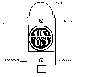
- Is it true that there are advantages to using trickle voltage heating rather than conventional space heaters? If so, what are these advantages?
A: Yes, trickle voltage heating has some distinct advantages, especially when applied in the field after the motor is built. Trickle voltage heating does not require removal and dismantling of the motor. In addition, it compares favorably in cost, provides improved heat distribution, and does not require additional wiring to the motor. Specifications for adding trickle voltage heating are available from the Product Service Department.
- What is vibration banding?
A: Banding is a method of dividing the frequency range into frequency bands and applying a vibration limit to each individual band. Banding recognizes that the vibration level at various frequencies is a function of the source of excitation and is grouped, or banded, in multiples of rotational frequency.
- Please explain the unfiltered vibration limits for standard machines.
A: For standard machines mounted resiliently, unfiltered vibration should not exceed the velocity levels shown in the top curve of figure 10a. For example, the limits at rotational frequency are shown in Table 11:
Table 11: Unfiltered Vibration Limits
Speed, rpm
Rotational Frequency, Hz
Velocity, in/s peak (mm/s)
3600
60
0.15 (3.8)
1800
30
0.15 (3.8)
1200
20
0.15 (3.8)
900
15
0.12 (3.0)
720
12
0.09 (2.3)
600
10
0.08 (2.0)
- What types of winding temperature detectors are utilized on U.S. MOTORS® brand products?
A: Specific types of winding temperature detectors include thermostats, RTD’s, thermistors, and thermocouples. Following is a brief description of each.
Winding thermostats are snap action, bi-metallic, temperature actuated switches. Their purpose is to activate a warning device, or simply shut down the motor upon excessive winding temperatures, when wired into the motor control circuit.
Thermostats are made either with contacts that are normally closed (open at high temperatures) or contacts that are normally open (closed at high temperatures). The thermostat temperature switch point is pre-calibrated by the manufacturer and is not adjustable. Reset is automatic after a decrease in temperature. Thermostats are normally installed in the connection end turns of the motor winding. Standard procedure is to wire three thermostats together in a set, with one thermostat embedded in each phase of the winding. Open thermostats are normally wired in parallel, while closed thermostats are wired in series. Refer to the figure below for further explanation

As seen in the figure above, only two leads come out to the motor outlet box. The leads of a normally closed (N.C. thermostat) are marked P1 and P2. Those of a normally open thermostat are marked P3 and P4.
Refer to the table below (Table 6) for thermostat alarm and shutdown temperatures.
Table 6: Thermostat Temperature Chart
Temperatures shown in ° C
Service Factor
1.00
1.15 and up
Purpose
Alarm
Shutdown
Alarm
Shutdown
Temp. Rise Class
A
B
F
A
B
F
A
B
F
A
B
F
Open Motors
N.O.
95
118
140
106
132
150
106
132
150
118
140
160
Without
N.C.
100
120
140
110
130
150
110
130
150
120
140
160
Ducts:
N.C. (R&T)
100
120
140
110
130
150
110
130
150
120
140
160
Open Motors
N.O.
106
132
150
118
140
160
118
140
150
132
150
160
With Ducts &
N.C.
110
130
150
120
140
160
120
140
150
130
150
160
TEFC Motors:
N.C. (R&T)
110
130
150
120
140
160
120
140
150
130
150
160
RTD’s (Resistance Temperature Detectors) are precision, wire-wound resistors, with a known temperature resistance characteristic. We use flat, molded strip type RTD’s that are only .030 inch thick. RTD’s are installed in the slot portion of form wound motors, and in either the slot or end turns of mush wound motors.
RTD’s used in motor windings are either 10 ohm, 100 ohm, or 120 ohm. Each type of RTD has its own specific resistance characteristic. The basic detectors are listed below in Table 7.
Table 7: Winding RTD’s
OHMS
ELEMENT
# LEADS
10 Ohms at 25° C
Copper Wire
3
100 Ohms at 0° C
Platinum Wire
3
120 Ohms at 0° C
Nickel Wire
2*
* Also available with 3 leads.
All the RTD leads are brought out to a motor outlet box. RTD’s leads are identified in sets, using C1, T1, T1, and C11, T11, T11 for the same phase. Since leads are always brought to terminal strips, the leads are terminated with fork-tongue terminals.
See alarm and trip temperatures based on the motor service factor, HP rating, and class of temperature rise.
Winding Thermistors
A thermistor is a non-linear resistance temperature detector, made from semi-conducting material. We utilize positive temperature coefficient (PTC) type thermistors, which have a resistance that increases with increasing temperature. Each individual thermistor has its own unique resistance vs. temperature characteristic. Thermistors are normally installed in the end turns of the motor. Depending upon the controller, they are wired either in series or in a ‘common lead circuit’. Both circuits are shown below.

The following is a brief description of the controllers and thermistors supplied by various companies:
Power Control Corporation (PCC)
In the past, we supplied PCC 600, 900, 8000, and 9000 series thermistors. We now use only the 8000 series thermistors. A maximum of three PCC 8000 series thermistors are installed in the common lead circuit configuration. Do not install them in series, or false tripping will result. PCC makes numerous controllers, including a special controller for the therma-sentry system. The PCC controller brand name is ‘MOTOGUARD’. For non-therma-sentry PCC thermistors, the thermistors are internally wired in the common lead configurations with the leads marked TM5, TM6, TM7, and TM8. Lead TM5 is the common lead.
Texas Instrument (TI)
TI currently uses 4BA and 7BA series, PTC thermistors. The 4BA series thermistors are normally used on new and rewound motors and contain a copper heat collector for a fast response time. The 7BA series is normally used on existing motors, and contains only a small thermistor bead to ease installation. TI thermistors are wired in series. Three thermistors may be installed in series without false tripping the controller. Our procedure is to bring out all six leads and make the series connection in the outlet box. The thermistor lead pairs are marked TM1, TM2, and TM3. The standard TI controller is a 50AA control module.
Siemens
We presently use a Siemens Q63100-P, PTC thermistor. Siemens thermistors must be wired in series. Six thermistors may be wired in series without false tripping the controller. Our standard procedure is to install three thermistors in series and bring all six leads out, making the series connection in the outlet box. The thermistor lead pairs are marked TM1, TM2, and TM3. The Siemens standard controller is a 3UN tripping unit control module, which has an N.O. and an N.C. contact.
The following table (Table 8) shows alarm and shutdown temperatures (in ° C) for 1.0 and 1.15 SF thermistors, based on the required class of temperature rise.
The new Thermasentry® system utilizes Siemens B59100M thermistors connected in series and a Siemens 3RN1010 controller.
Table 8: Thermistor Temperature Setting Chart
Temperatures shown in ° C
Service Factor
1.0
1.15 - UP
Purpose
ALARM
SHUTDOWN
ALARM
SHUTDOWN
Class of Temp. Rise
A
B
F
A
B
F
A
B
F
A
B
F
Open Motors w/o Ducts
PCC, PTC 8000
105
115
145
115
125
155
105
125
155
115
135
165
TI, 4BA Series
105
115
145
115
125
155
105
125
155
115
135
165
TI, 7BA Series
105
115
145
115
125
155
105
125
155
115
135
165
Siemens
100
120
140
110
130
155
110
130
155
120
140
160
Open w/Ducts and TEFC Motors
PCC, PTC 8000
105
125
155
115
135
165
115
135
155
125
145
165
TI, 4BA Series
105
125
155
115
135
165
115
135
155
125
145
165
TI, 7BA Series
105
125
155
115
135
165
115
135
155
125
145
165
Siemens
110
130
150
120
140
160
120
140
155
130
150
160
Thermocouples
A thermocouple is a pair of dissimilar conductors joined at one point, in a way that causes an electromotive force (EMF) to develop due to the thermoelectric effects. Any given set of thermocouple wires has a known EMF vs. temperature characteristic. Thermocouples are only able to generate a low-voltage, low-power signal in the millivolt range. There are many types of thermocouples. Standard types include copper-constantan, chromel-constantan, and iron-constantan. Thermocouples are normally installed in the slot between coil sides, on both mush wound and form wound motors. However, if necessary, they can also be installed in the end turns. The standard quantity of thermocouples is six, installed two per phase. If quantity-3 thermocouples are specified, leads are marked TC1, TC2, and TC3. If quantity-6 are specified, leads are marked TC1, TC2, TC3, and TC11, TC22, TC33, such that TC1 and TC11, etc. are in the same phase.
See alarm settings for alarm and trip temperatures based on the motor service factor, HP rating, and class of temperature rise.